Transcription of The Two Faces of Q - W7ZOI Site
1 The Two Faces of QWes Hayward, W7ZOI , November, :14 Dec10, 29 Dec10, 14, 2015. Seeaddendumat document home-lab measurements of q only evaluate an LC then tend to associate the resulting Q with inductor losswhile capacitor Q is assumed to be quite assumptionis now in greater doubt, especially with SMT aneffort to isolate capacitor Q from inductor Q, some well specifiedhigh Q mica capacitors were purchased and used allowed evaluation of some inductors thatthen become "standards" that can be used to evaluate available capacitor types were investigated and someinductor Q measurements were 've always been interested in the design of frequency selective filters andimpedance transforming connected to this has been along standing interest in the measurement of q with some of this work havingappeared on this web report is anupdate (and summary)
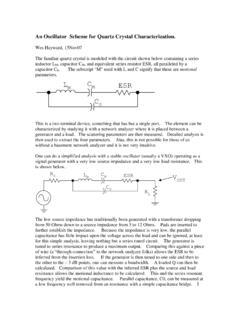
2 Of parts ofthat figure shows an ideal LC tuned circuit, or separatedocument shows some of the mathematical Resonator QThree methods for Q measurement are briefly discussed details canall be derived from a simplemodelfor resonator Q where all losses arerepresented by a resistor value isA subscript"R" appears on both the resistor and the Q term, indicating that these areresonatorrelated details, seeIntroduction to RF Design, ARRL,1994, p58, or many other classicengineering text threemeasurement methods presented are allresonator measurements and are notnecessarily determinations of component analysis done in thisdiscussion uses series resistors to model loss, but parallel resistors canalso beused with no change in Q of a tuned circuit is equal to the center frequency divided by the 3 dBbandwidth of that is not a definition or a rule of thumb, but isaderived resonator characteristic can be used to measure the Qof a LC tuned circuit embedded in the following circuit.
3 The basiccircuit to be measured is the tuned circuit builtfrom L and form a parallel tuned circuit and are then coupled to a 50 Ohmsource and a 50 Ohm load with coupling capacitors two capacitorsshould be nearly identical in value, should themselves have high Q, and shouldbemuch smaller in capacitance than , Cc=C0 experimental procedure is used:a)The source is tuned to produce a maximum output centerfrequency,F0, and the insertion loss is loss is just thepoweravailablefrom the generator to the load divided by the power delivered to powerfrom the generator is measured by removing thefilter (the part of the circuit between the dotted lines) and replacing it with a"through" connection, attaching the generator directly to the )
4 The insertion loss should be 30 dB or the loss is less than 30 dB,the values of Cc should be decreased and the procedure should be to keep the Cc values approximately equal to each )Assuming IL> 30 dB,the exact value of IL is carefully measured generator is then tuned on either side of the peak to find theplaces where the loss is (IL+3 dB.)This requires careful )The difference between the two 3 dB frequencies isB, this number is determined, the bandwidth is known and the Q can becalculated asQ=F0/BThe reason for picking an insertion loss of 30dB or more is that this produces aQ number that represents the intrinsic loss in the is called theunloaded Q, or Qu.
5 And is the value we IL well under 30 dB wouldgenerate a lower Q value that is partially determined by tunedcircuit loadingby the external source and loaded BW would be wider than theunloaded center frequency for the composite filter will be slightlylower than the raw resonator formed by L and C0 owing to the two extracapacitors variation of this method uses larger values of Cc, which yield lower lossthrough the measurement mathematical correction is then applied toextract the unloaded Q is now important to obtain a bettermeasurement of the actual insertion information in IRFD, ARRL1994, p58, can be used for this workers do a similar measurement where a source is weakly coupled tothe resonator and the output is sampled with an oscilloscope and 10X method can provide reasonable results if done with great care.
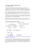
6 But can alsobe compromised by the loss in the scope prefer to avoid thisuncertainty by using a measurement scheme where all loads are well second scheme for measuring the Q of a resonator is to configure the Land C as a series tuned series tuned circuit is then attached as aparallel connected trap as shown source generator is tuned to produce the lowest output in the load, whichoccurs as a narrow following procedure is used:a)The generator is tuned to produce the notch frequency iscarefully )The attenuation of this notch filter is carefully can beread directly if a network analyzer is used as the source and a signalgenerator is used with a spectrum analyzer, power meter, or 50 Ohm terminatedoscilloscope as the load, the attenuation can be obtained by removing the trapfilter and inserting a step attenuator in its variable attenuator, whichshould have 1 dB or finer steps, is adjusted to produce the same response thatthe filter may be necessary to interpolate to obtain resolution ofabout dB for )
7 The trap is disassembled and the capacitance of C0 is usuallydo this with an LC meter from AADE.(See "Almost All Digital Electronics"on the web.)d)The measured data is then used to calculate the detail isgiven on page of EMRFD.(Experimental Methods in RF Design,ARRL, 2003.)The equation isIt is important that the source impedance used for this measurement be wellknown at Z0, usually 50 there is uncertainty, it is best to place a padright at the coax connector where the trap is usually use a 14 dB pad,even whenusing a network analyzer for the is much more important than load impedance for this method has the advantage over the direct bandwidth method that only onecareful level measurement is is the determination of theattenuation tend to use method 2 for routine measurements.
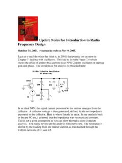
8 And usethe bandwidth scheme (method 1) to confirm the experimental variation of this method uses a parallel tuned circuit connected as a is not as handy, for neither component is attached to isusually handy to have C0 attached to fundamental circuit used in commercial Q-Meters is shown below andthis is a third are two critical features to this first is a very low is realized with a carefully built transformer in theinstruments found on the surplus market. It may be possible to get good low Zresults with modern wide bandwidth operational amplifiers.
9 (That's anexperiment on my list.)The other difficult, but important element in buildinga Q meter is the capacitor, C, usually a cap should have thehighest possible workers have reported good results with JenningsVacuum Variable the capacitor is good enough, the measuredresults will faithfully describe the Q of the manual for the HP-4342A QMeter is often sold on the web and offers interesting this is the last commercially built Q meter and know of nothing on themarket at the present Q meters have largely been replacedby network the Two FacesOur home-lab measurements are all done on resonators, usually fabricated fromdiscrete inductors and , we have assumed that thecapacitor Q has been sufficiently high that it can be ignored.
10 Attributing all lossto the is a reasonable viewpoint in some, but not all particular, many surface mount capacitors are sufficiently poor that theyseverely compromise resonator really must be able to measure bothinductors and ideal LC is modeled, as a resonator, with a single resistor, is the value that would generate the observed Q if the L and C wereotherwise resistor value is just the ratio of the inductive reactanceto resonator Q, as presented in an earlier resonator resistor isdrawn in series with the inductor in the above figure, but it is clearly in serieswith both the L and Q for the inductor and the capacitors alone is modeled with , these resistors are just the reactance of the elements dividedby the Q of that should emphasize that the these resistors are justmodels, usually frequency is a sum of the two component related resistors.