Transcription of Thermoelectric Cooler (TEC) Controller ... - Analog Devices
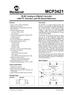
1 Thermoelectric Cooler (TEC) Controller Data Sheet ADN8831 Rev. C Document Feedback Information furnished by Analog Devices is believed to be accurate and reliable. However, no responsibility is assumed by Analog Devices for its use, nor for any infringements of patents or other rights of third parties that may result from its use. Specifications subject to change without notice. No license is granted by implication or otherwise under any patent or patent rights of Analog Devices . Trademarks and registered trademarks are the property of their respective owners. One Technology Way, Box 9106, Norwood, MA 02062-9106, Tel: 2005 2019 Analog Devices , Inc. All rights reserved. Technical Support FEATURES Two integrated zero drift, rail-to-rail, chop amplifiers TEC voltage and current operation monitoring Programmable TEC maximum voltage and current Programmable TEC current heating and cooling limits Configurable PWM switching frequency up to 1 MHz Power efficiency.
2 > 90% Temperature lock indication Optional internal or external clock source Clock phase adjustment for multiple drop operation Supports negative temperature coefficient (NTC) thermistors or positive temperature coefficient (PTC) resistance thermal detectors (RTDs) 5 V typical and optional 3 V supplies Standby and shutdown mode availability Adjustable soft start feature 5 mm 5 mm 32-lead LFCSP APPLICATIONS Thermoelectric Cooler (TEC) temperature control DWDM optical transceiver modules Optical fiber amplifiers Optical networking systems Instruments requiring TEC temperature control GENERAL DESCRIPTION The ADN88311 is a monolithic TEC Controller . It has two inte-grated, zero drift, rail-to -rail comparators, and a PWM driver. A unique PWM driver works with an Analog driver to control external selected MOSFETs in an H-bridge. By sensing the thermal detector feedback from the TEC, the ADN8831 can drive a TEC to settle the programmable temperature of a laser diode or a passive component attached to the TEC module.
3 The ADN8831 supports NTC thermistors or positive tempera-ture coefficient (PTC) RTDs. The target temperature is set as an Analog voltage input either from a DAC or from an external resistor divider driven by a reference voltage source. A proportional integral differential (PID) compensation network helps to quickly and accurately stabilize the ADN8831 thermal control loop. An adjustable PID compensation network example is described in the AN-695 Application Note, Using the ADN8831 TEC Controller Evaluation Board. A typical reference voltage of V is available from the ADN8831 for thermistor temperature sensing or for TEC voltage/current measuring and limiting in both cooling and heating modes. FUNCTIONAL BLOCK DIAGRAM AMPLIFIERChop2 AMPLIFIERChop1IN1 PIN1 NOUT1IN2 PIN2 NOUT2 LIMITER/MONITORREFSOFT STARTSHUTDOWNOSCILLATORTMPGDVREFSS/SBPHA SEFREQSYNCI/SDLINEARMOSFETDRIVERPWMMOSFE TDRIVERLFBLPGATELNGATESFBSPGATESNGATECOM PSWSWCOMPOSCSYNCOCONTROLILIMCILIMHITECVL IMVTECCS04663-001 Figure 1.
4 1 Product is covered by Patent No. 6,486,643. ADN8831 Data Sheet Rev. C | Page 2 of 18 TABLE OF CONTENTS Features .. 1 Applications .. 1 General Description .. 1 Functional Block Diagram .. 1 Revision History .. 2 Detailed Block Diagram .. 3 Specifications .. 4 Electrical Characteristics .. 4 Absolute Maximum Ratings .. 6 Thermal Characteristics .. 6 ESD Caution .. 6 Pin Configuration and Function Descriptions .. 7 Typical Performance Characteristics .. 9 Theory of Operation .. 11 Oscillator Clock Frequency .. 12 Oscillator Clock Phase .. 12 Temperature Lock Indicator .. 13 Soft Start on Power-Up .. 13 Shutdown Mode .. 13 Standby Mode .. 13 TEC Voltage/Current Monitor .. 13 Maximum TEC Voltage Limit .. 13 Maximum TEC Current Limit .. 14 Applications Information .. 15 Signal Flow .. 15 Thermistor Setup .. 15 Thermistor Amplifier (Chop1) .. 15 PID Compensation Amplifier (Chop2).
5 16 MOSFET Driver Amplifier .. 17 Outline Dimensions .. 18 Ordering Guide .. 18 REVISION HISTORY 9/2019 Rev. B to Rev. C Changes to Figure 3 .. 7 Changes to Table 4 .. 8 Updated Outline Dimensions .. 18 Changes to Ordering Guide .. 18 9/2018 Rev. A to Rev. B Added Patent Information .. 1 8/2012 Rev. 0 to Rev. A Changes to Features and General Description Sections .. 1 Moved Figure 2 .. 3 Changes to Figure 2 .. 3 Changes to Table 1 .. 4 Changes to Table 2 and Table 3 .. 6 Changes to Figure 3 and Table 4 .. 7 Changes to Theory of Operation Section and Figure 12 .. 11 Changes to Figure 14 and Figure 11 Changes to Oscillator Clock Frequency Section and Oscillator Clock Phase Section .. 12 Changes to Soft Start on Power-Up Section, Shutdown Mode Section, Standby Mode Section, and TEC Voltage/Current Monitor Section .. 13 Changes to Figure 17 .. 15 Changes to PID Compensation Amplifier (Chop2) Section.
6 16 Changes to MOSFET Driver Amplifier Section and Figure 21 .. 17 Updated Outline Dimensions .. 18 Changes to Ordering Guide .. 18 9/2005 Revision 0: Initial Version Data Sheet ADN8831 Rev. C | Page 3 of 18 DETAILED BLOCK DIAGRAM 2k 10k STARTSB250mVOSCILLATORSDSDDETECT13 ITECILIMCILIMH100k 100k 20k 20k LFBLINEAR AMPLIFIERLPGATELNGATELFBVBVC23 VBgm3gm2gm1VC20k 20k 20k 20k , VDD > , VDD < 20k 20k 5k 25k VREF04663-0035k 1k AVDDPHASETMPGDAGNDFREQSYNCOSYNCI/SDSS/SB Figure 2. Detailed Block Diagram ADN8831 Data Sheet Rev. C | Page 4 of 18 SPECIFICATIONS ELECTRICAL CHARACTERISTICS VDD = V to V, TA = 25 C, unless otherwise noted. Table 1. Parameter1 Symbol Test Conditions/Comments Min Typ Max Unit PWM OUTPUT DRIVER Output Transition Time tR, tF CL = 3300 pF 20 ns Nonoverlapping Clock Delay 40 80 ns Output Resistance RO (SNGATE, SPGATE)
7 IL = 10 mA, VDD = V 6 Output Voltage Swing2 SFB VLIM = VREF 0 VDD V LINEAR OUTPUT AMPLIFIER Output Resistance RO, LNGATE IOUT = 2 mA, VDD = V 200 RO, LPGATE IOUT = 2 mA, VDD = V 100 Output Voltage Swing2 LFB 0 VDD V POWER SUPPLY Power Supply Voltage VDD V Supply Current ISY PWM not switching 8 12 mA 40 C TA +85 C 15 mA Shutdown Current ISD SYNCI/SD = 0 V
8 8 A Soft Start Charging Current ISS VSS = 0 V 8 A Undervoltage Lockout3 UVLO Low to high threshold V Standby Current ISB SYNCI/SD = VDD, SS/SB = 0 V 2 mA Standby Threshold VSB SYNCI/SD = VDD 150 200 mV ERROR/COMPENSATION AMPLIFIERS Input Offset Voltage VOS1 VCM1 = V, VIN1P VIN1M 10 100 V VOS2 VCM2 = V, VIN2P VIN2M 10 100 V Input Voltage Range VCM1, VCM2 0 VDD V Common-Mode Rejection Ratio CMRR1, CMRR2 VCM1, VCM2 = V to VDD V 120 dB Output Voltage High VOH1, VOH2 VDD V Output Voltage Low VOL1, VOL2 25 mV Power Supply Rejection Ratio PSRR1, PSRR2 V VDD V 110 dB Output Current IOUT1, IOUT2 Sourcing and sinking 5 mA Gain Bandwidth Product GBW1, GBW2 VOUT = V to (VDD 1 V)
9 2 MHz OSCILLATOR Sync Range fCLK SYNCI/SD connected to external clock 300 1000 kHz Oscillator Frequency fCLK COMPOSC = VDD, RFREQ = 118 k , SYNCI/SD = VDD, VDD = V 800 1000 1250 kHz Nominal Free-Run Oscillation Frequency fCLK-NOMINAL COMPOSC = VDD, SYNCI/SD = VDD 200 1000 kHz Phase Adjustment Range2 CLK VPHASE = V, fSYNCI/SD = 1 MHz 50 Degrees VPHASE = V, fSYNCI/SD = 1 MHz 330 Degrees Phase Adjustment Default CLK PHASE = open 180 Degrees REFERENCE VOLTAGE Reference Voltage VREF IREF = 2 mA V IREF = 0 mA V Data Sheet ADN8831 Rev.
10 C | Page 5 of 18 Parameter1 Symbol Test Conditions/Comments Min Typ Max Unit LOGIC Controls Logic Low Output Voltage VOL TMPGD, SYNCO, IOUT = 0 A V Logic High Output Voltage VOH TMPGD, SYNCO, IOUT = 0 A VDD V Logic Low Input Voltage VIL V Logic High Input Voltage VIH 3 V Output High Impedance VDD = V 35 Output Low Impedance VDD = V 20 Output High Impedance VDD = V 50 Output Low Impedance VDD = V 25 TEC CURRENT MEASUREMENT ITEC Gain AV, ITEC (VITEC VREF/2) / (VLFB VCS)