Transcription of Two-Stage Power Amplifier Module, 10 MHz ... - Analog …
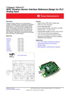
1 Two-Stage Power Amplifier module , 10 MHz to 6 GHz Data Sheet HMC-C075 Rev. C Document Feedback Information furnished by Analog devices is believed to be accurate and reliable. However, no responsibility is assumed by Analog devices for its use, nor for any infringements of patents or other rights of third parties that may result from its use. Specifications subject to change without notice. No license is granted by implication or otherwise under any patent or patent rights of Analog devices . Trademarks and registered trademarks are the property of their respective owners. One Technology Way, Box 9106, Norwood, MA 02062-9106, Tel: 2016 Analog devices , Inc. All rights reserved. Technical Support FEATURES High gain: 25 dB High 1 dB compression (P1dB) output Power : 29 dBm High output third-order intercept (IP3): 42 dBm Regulated supply and bias sequencing SMA connectors Operating temperature: 40 C to +70 C APPLICATIONS Telecommunications infrastructure Test instrumentation Military and space Electronic warfare (EW) Electronic countermeasures (ECM) Radar Test equipment FUNCTIONAL BLOCK DIAGRAM VOLTAGEREGULATORVOLTAGEREGULATORRFIN1 RFOUT23 GND+V DC V DC45 HMC-C07513952-001 Figure 1.
2 GENERAL DESCRIPTION The HMC-C075 is a Two-Stage Power Amplifier module that operates between 10 MHz and 6 GHz. The Amplifier provides 25 dB of gain, 42 dBm of output IP3, and 29 dBm of output Power at 1 dB gain compression, while consuming only 740 mA from a 15 V supply. The HMC-C075 is ideal for EW, ECM, radar, and test equipment applications The Amplifier inputs/outputs (I/Os) are dc blocked and internally matched to 50 . Integrated voltage regulators allow flexible biasing of both the negative and positive supply pins, while internal bias sequencing and active bias control allows robust operation and stable performance over temperature. HMC-C075 Data Sheet Rev. C | Page 2 of 10 TABLE OF CONTENTS Features .. 1 Applications.
3 1 Functional Block Diagram .. 1 General Description .. 1 Revision History .. 2 Specifications .. 3 Absolute Maximum Ratings .. 4 ESD Pin Configuration and Function Descriptions ..5 Typical Performance Characteristics ..6 Theory of Operation ..8 Applications information ..9 Outline Dimensions .. 10 Ordering Guide .. 10 REVISION HISTORY 1/16 Revision C: Initial Ve r s i o n Data Sheet HMC-C075 Rev. C | Page 3 of 10 SPECIFICATIONS Bias voltages = +15 V and 5 V; baseplate temperature = 25 C, unless otherwise noted. Table 1. Parameter Min Typ Max Unit Test Conditions/Comments FREQUENCY RANGE 6 GHz GAIN GHz to 1 GHz 21 25 dB 1 GHz to 3 GHz 21 25 dB 3 GHz to 6 GHz 18 23 dB GAIN FLATNESS 3 dB GAIN VARIATION OVER TEMPERATURE dB/ C NOISE FIGURE 1 GHz to 3 GHz 8 dB 3 GHz to 6 GHz 5 dB 1 dB COMPRESSION (P1dB) GHz to 1 GHz 24 28 dBm 1 GHz to 3 GHz 27 30 dBm 3 GHz to 6 GHz 26 29 dBm OUTPUT THIRD-ORDER INTERCEPT (IP3) GHz to 1 GHz 42 dBm 1 GHz to 3 GHz 43 dBm 3 GHz to 6 GHz 41 dBm S AT U R AT E D OUTPUT Power (PS AT)
4 30 dBm RETURN LOSS Input 12 dB Output 14 dB SUPPLY INPUT +V DC 15 V V DC 5 V CURRENT +V DC 740 900 mA +V DC = +15 V, V DC = 5 V V DC 5 10 mA HMC-C075 Data Sheet Rev. C | Page 4 of 10 ABSOLUTE MAXIMUM RATINGS Table 2. Parameter Rating 15 V Bias Line 16 V 5 V Bias Line 16 V Radio Frequency (RF) Input Level 10 dBm Operating Temperature Range 40 C to +70 C Storage Temperature Range 55 C to +150 C ESD Sensitivity, Human Body Model (HBM) Class IA Thermal Resistance C/W Stresses at or above those listed under Absolute Maximum Ratings may cause permanent damage to the product. This is a stress rating only; functional operation of the product at these or any other conditions above those indicated in the operational section of this specification is not implied.
5 Operation beyond the maximum operating conditions for extended periods may affect product reliability. ESD CAUTION Data Sheet HMC-C075 Rev. C | Page 5 of 10 PIN CONFIGURATION AND FUNCTION DESCRIPTIONS 1 RFIN2 RFOUT345 GND+V DCHMC-C075 V DC13952-002 Figure 2. Pin Configuration Table 3. Pin Function Descriptions Pin No. Mnemonic Description 1 RFIN RF Input Connector, SMA Female, Field Replaceable. This pin is ac-coupled and matched to 50 . 2 RFOUT RF Output Connector, SMA Female, Field Replaceable. This pin is ac-coupled and matched to 50 . 3 GND Power Supply Ground. 4 +V DC Positive Supply Voltage, 14 V to 16 V. 5 V DC Negative Supply Voltage, 5 V to 16 V. HMC-C075 Data Sheet Rev. C | Page 6 of 10 TYPICAL PERFORMANCE CHARACTERISTICS Bias voltages = +15 V and 5 V; baseplate temperature = 25 C, unless otherwise noted.
6 3020100 10 20 30 4001234567 RESPONSE (dB)FREQUENCY (GHz)INPUT RETURN LOSSGAINOUTPUT RETURN LOSS13952-003 Figure 3. Gain and Input/Output Return Loss vs. Frequency 0 5 10 15 20 25 30 INPUT RETURN LOSS (dB)01234567 FREQUENCY (GHz)+70 C+25 C 40 C13952-004 Figure 4. Input Return Loss vs. Frequency for Various Temperatures 0 80 60 70 50 30 10 40 20 ISOLATION (dB)01234567 FREQUENCY (GHz)+70 C+25 C 40 C13952-005 Figure 5. Isolation vs. Frequency for Various Temperatures 40353025201510 GAIN (dB)01234567 FREQUENCY (GHz)+70 C+25 C 40 C13952-006 Figure 6. Gain vs. Frequency for Various Temperatures 0 40 30 35 25 15 5 20 10 OUTPUT RETURN LOSS (dB)01234567 FREQUENCY (GHz)+70 C+25 C 40 C13952-007 Figure 7. Output Return Loss vs. Frequency for Various Temperatures 12106842 NOISE FIGURE (dB)01234567 FREQUENCY (GHz)+70 C+25 C 40 C13952-008 Figure 8.
7 Noise Figure vs. Frequency for Various Temperatures Data Sheet HMC-C075 Rev. C | Page 7 of 10 3422242628303201234567 OUTPUT P1dB (dBm)FREQUENCY (GHz)+70 C+25 C 40 C13952-009 Figure 9. Output P1dB vs. Frequency for Various Temperatures 60202530354045505501234567IP3 (dBm)FREQUENCY (GHz)+70 C+25 C 40 C13952-010 Figure 10. IP3 vs. Frequency for Various Temperatures 30 40 30 20020 (dB)FREQUENCY (GHz)13952-011 INPUT RETURN LOSSGAINOUTPUT RETURN LOSS Figure 11. Gain, Input Return Loss, and Output Return Loss vs. Frequency 3422242628303201234567 PSAT (dBm)FREQUENCY (GHz)+70 C+25 C 40 C13952-012 Figure 12. PSAT vs. Frequency for Various Temperatures 3501051520253075074074574474374274174674 7748749 10 6 22610 POUT (dBm), GAIN (dB), PAE (%)CURRENT (mA)INPUT Power (dBm)GAINPOUTPAECURRENT13952-013 Figure 13.
8 Output Power (POUT), Gain, and Power Added Efficiency (PAE) vs. Input Power (dBm)FREQUENCY (GHz)+70 C+25 C 40 C13952-014 Figure 14. Output IP3 vs. Frequency HMC-C075 Data Sheet Rev. C | Page 8 of 10 THEORY OF OPERATION The HMC-C075 package contains four mounting locations for screws to secure the Amplifier package in dynamic applications and for thermal contact. Attach the Amplifier to a heat sink of a suitable size such that, during operation, the backside case temp-erature never exceeds 70 C. Operation of the device at backside case temperatures greater than 70 C results in reduced life of the device. Prior to applying dc voltages, terminate both the RF input and the RF output to 50 . Never disconnect the RF output when dc voltages are applied to the device.
9 Data Sheet HMC-C075 Rev. C | Page 9 of 10 APPLICATIONS INFORMATION The HMC-C075 is a connectorized Amplifier module designed with two stage amplifiers to deliver 29 dBm of typical Power with a 25 dB gain from GHz to 6 GHz. The bias of the internal amplifiers is supplied by 15 V and 5 V dc sources that Power internal voltage regulators. The HMC-C075 features built-in bias sequencing and active bias control to prevent damage to the amplifiers and to maintain stable gain over temperature. The HMC-C075 is built in a miniature module with SMA connectors for RF input and output, and robust feedthroughs for bias and ground return. To turn on the Amplifier , complete the following steps: 1. Ve r i f y that the dc connections are correct.
10 2. Verify that the RF input Power is off. 3. Apply V DC to the supply pin. 4. Apply +V DC to the supply pin. 5. Apply the RF input, ensuring that the Power level is correct. To turn off the Amplifier , complete the following steps: 1. Tu r n t h e RF input off. 2. Tu r n o f f t h e +V DC supply. 3. Tu r n o f f t h e V DC suppl y. HMC-C075 Data Sheet Rev. C | Page 10 of 10 OUTLINE DIMENSIONS 12-10-2015-APKG-000000 CONTROLLING DIMENSIONS ARE IN INCHES; MILLIMETER DIMENSIONS(IN PARENTHESES) ARE ROUNDED-OFF INCH EQUIVALENTS FORREFERENCE ONLY AND ARE NOT APPROPRIATE FOR USE IN ( ) ( ) ( )END VIEWSIDE VIEWTOP ( ) ( ) ( ) ( ) ( ) ( ) ( ) ( ) ( ) ( ) ( ) ( ) ( ) ( ) ( ) ( ) ( ) ( ) ( ) Figure 15. 5-Lead module with Connector Interface [ module ] (ML-5-2) Dimensions shown in inches and (millimeters) ORDERING GUIDE Model Temperature Range Package Description Package Option HMC-C075 40 C to +70 C 5-Lead module with Connector Interface [ module ] ML-5 -2 2016 Analog devices , Inc.