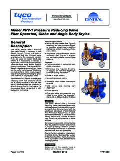
Transcription of Typical Applications Features General Description
1 ATTENUATORS - DIGITAL - dB GaAs MMIC 1-BIT DIGITALPOSITIVE CONTROL ATTENUATOR, DC - 10 GHzFor price, delivery, and to place orders: analog devices , Inc., One Technology Way, Box 9106, Norwood, MA 02062-9106 Phone: 781-329-4700 Order online at Support: Phone: 1-800- analog -DInformation furnished by analog devices is believed to be accurate and reliable. However, no responsibility is assumed by analog devices for its use, nor for any infringements of patents or other rights of third parties that may result from its use. Specifications subject to change without notice. No license is granted by implication or otherwise under any patent or patent rights of analog devices . Trademarks and registered trademarks are the property of their respective owners. Functional DiagramElectrical Specifications, TA = +25 C, With Vdd = +5V & Vctl = 0/+5 VThe HMC802 ALP3E is ideal for both RFand IF Applications : Test Equipment and Sensors ISM, MMDS, WLAN, WiMAX, WiBro Microwave Radio & VSAT Cellular Infrastructure dB Typical Step ErrorLow Insertion Loss: 3 dBHigh IP3: +55 dBmSingle Control LineTTL/CMOS Compatible ControlSingle +5V Supply16 Lead 3x3mm SMT Package: 9mm The HMC802 ALP3E is a broadband bidirectional 1-bit GaAs IC digital attenuator in a low cost leadless sur-face mount package.
2 This single positive control line digital attenuator utilizes off chip AC ground capac-itors for near DC operation, making it suitable for a wide variety of RF and IF Applications . Covering DC to 10 GHz, the insertion loss is less than 3 dB Typical and attenuation accuracy is excellent at dB typ-ical. The attenuator also Features a high IIP3 of +55 dBm. One TTL/CMOS control input is used to select the attenuation state and a single Vdd bias of +5V is required. ParameterFrequency (GHz) LossDC - 4 GHz4 - 8 GHz8 - 10 RangeDC - 10 GHz20dBReturn Loss (RF1 & RF2, Both States)DC - 6 GHz6 - 10 GHz2515dBdBAttenuation Accuracy: (Referenced to Insertion Loss)1DC - 6 GHz6 - 8 GHz8 - 10 + + + + + +1. 2dBdBInput Power for dB CompressionDC - 10 GHz27dBmInput Third Order Intercept Point(Two-Tone Input Power= 14 dBm Each Tone)DC - 10 GHz55dBmSwitching CharacteristicstRISE, tFALL (10/90% RF)tON, tOFF (50% CTL to 10/90% RF)DC - 10 GHz7090nsns1.
3 STEP SIZE IS 20DB FOR ALL FREQUENCYT ypical ApplicationsFeaturesGeneral DescriptionFor price, delivery, and to place orders: analog devices , Inc., One Technology Way, Box 9106, Norwood, MA 02062-9106 Phone: 781-329-4700 Order online at Support: Phone: 1-800- analog -DATTENUATORS - DIGITAL - dB GaAs MMIC 1-BIT DIGITALPOSITIVE CONTROL ATTENUATOR, DC - 10 GHzInput Return Loss Output Return Loss Insertion LossRelative AttenuationBit Error vs. FrequencyRelative Phase vs. Frequency-6-5-4-3-2-10024681012+25 C+85 C -40 CINSERTION LOSS (dB)FREQUENCY (GHz)-40-30-20-100024681012 INSERTION LOSS20 dBRETURN LOSS (dB)FREQUENCY (GHz)-40-30-20-100024681012 INSERTION LOSS20 dBRETURN LOSS (dB)FREQUENCY (GHz)-26-24-22-20-18-16-14024681012 NORMALIZED ATTENUATION (dB)FREQUENCY (GHz) ERROR (dB)FREQUENCY (GHz)-60-40-200204060024681012 RELATIVE PHASE (dB)FREQUENCY (GHz)For price, delivery, and to place orders: analog devices , Inc., One Technology Way, Box 9106, Norwood, MA 02062-9106 Phone: 781-329-4700 Order online at Support: Phone: 1-800- analog -DATTENUATORS - DIGITAL - dB GaAs MMIC 1-BIT DIGITALPOSITIVE CONTROL ATTENUATOR, DC - 10 GHzInput IP3 vs.
4 FrequencyInput IP3 vs. Frequency (Low Frequency Detail)Input Power for 1 dB CompressionTruth TableControl VoltageBias Voltage & CurrentVdd = +5 Vdc 10%Vdd(Vdc)I d d ( Ty p.)(mA) ConditionLow0 to + @ -1 A +2 to +5V @ 30 A : Vdd = +5 VControl Voltage InputAttenuation StateRF1 - RF2V1 HighReference Insertion LossLow20 dB203040506070024681012 INSERTION LOSS20 dBIP3 (dBm)FREQUENCY (GHz) LOSS20 dBIP3 (dBm)FREQUENCY (GHz)Input Power for dB Compression(Low Frequency Detail) INPUT POWER (dBm)FREQUENCY (GHz) INPUT POWER (dBm)FREQUENCY (GHz)For price, delivery, and to place orders: analog devices , Inc., One Technology Way, Box 9106, Norwood, MA 02062-9106 Phone: 781-329-4700 Order online at Support: Phone: 1-800- analog -DATTENUATORS - DIGITAL - dB GaAs MMIC 1-BIT DIGITALPOSITIVE CONTROL ATTENUATOR, DC - 10 GHzAbsolute Maximum RatingsOutline DrawingRF Input Power (DC - 10 GHz)+ dBmControl Voltage Range (V1)-1 to Vdd + 1 VBias Voltage (Vdd)+7 VdcChannel Temperature150 CContinuous Pdiss (T = 85 C) (derate 12 mW/ C above 85 C) WThermal Resistance (channel to ground paddle)7 7.
5 4 C/WStorage Temperature-65 to +150 COperating Temperature-40 to +85 CESD Sensitivity (HBM)Class 1 AELECTROSTATIC SENSITIVE DEVICEOBSERVE HANDLING PRECAUTIONSPart NumberPackage Body MaterialLead FinishMSL RatingPackage Marking [2]HMC802 ALP3 ERoHS-compliant Low Stress Injection Molded Plastic100% matte SnMSL3 [1]H802 AXXXX[1] Max peak reflow temperature of 260 C[2] 4-Digit lot number XXXXP ackage InformationNOTES:1. LEADFRAME MATERIAL: COPPER ALLOY2. DIMENSIONS ARE IN INCHES [MILLIMETERS]3. LEAD SPACING TOLERANCE IS NON-CUMULATIVE4. PAD BURR LENGTH SHALL BE MAXIMUM. PAD BURR HEIGHT SHALL BE PACKAGE WARP SHALL NOT EXCEED ALL GROUND LEADS AND GROUND PADDLE MUST BE SOLDERED TO PCB RF REFER TO HITTITE APPLICATION NOTE FOR SUGGESTED L AND PAT price, delivery, and to place orders: analog devices , Inc., One Technology Way, Box 9106, Norwood, MA 02062-9106 Phone: 781-329-4700 Order online at Support: Phone: 1-800- analog -DATTENUATORS - DIGITAL - dB GaAs MMIC 1-BIT DIGITALPOSITIVE CONTROL ATTENUATOR, DC - 10 GHzPin DescriptionsPin NumberFunctionDescriptionInterface Schematic1 VddSupply , 4, 9, 11 GNDT hese pins and the exposed ground paddle must be connected to RF/DC , 10RF1, RF2 These pins are DC coupled and matched to 50 Ohms.
6 Blocking capacitors are required. Select value based on lowest frequency of , 7, 8 ACG1, ACG2, ACG3 External capacitor to ground is required. Select value for lowest frequency of operation. Place capacitor as close to pins as , 12, 13, 15, 16N/CThe pins are not connected internally; however, all data shown herein was measured with these pins connected to RF/DC ground truth table and control voltage CircuitFor price, delivery, and to place orders: analog devices , Inc., One Technology Way, Box 9106, Norwood, MA 02062-9106 Phone: 781-329-4700 Order online at Support: Phone: 1-800- analog -DATTENUATORS - DIGITAL - dB GaAs MMIC 1-BIT DIGITALPOSITIVE CONTROL ATTENUATOR, DC - 10 GHzEvaluation PCBThe circuit board used in the application should use RF circuit design techniques. Signal lines should have 50 Ohm impedance while the package ground leads and exposed paddle should be connected directly to the ground plane similar to that shown.
7 A sufficient number of via holes should be used to connect the top and bottom ground planes. The evaluation circuit board shown is available from analog devices Inc. upon of Materials for Evaluation PCB EV1 HMC802 ALP3 [1]ItemDescriptionJ1, J2 PCB Mount SMA ConnectorJ3, J4DC ConnectorC11000 pF Capacitor, 0603 , C3100 pF Capacitor, 0402 - C6330 pF Capacitor, 0402 Digital AttenuatorPCB [2]121213 Evaluation PCB[1] Reference this number when ordering complete evaluation PCB[2] Circuit Board Material: Rogers 4350