Transcription of Ultralow Distortion IF Dual VGA Data Sheet AD8376
1 Ultralow Distortion IF dual VGA data Sheet AD8376 Rev. B Document Feedback Information furnished by analog devices is believed to be accurate and reliable. However, no responsibility is assumed by analog devices for its use, nor for any infringements of patents or other rights of third parties that may result from its use. Specifications subject to change without notice. No license is granted by implication or otherwise under any patent or patent rights of analog devices . Trademarks and registered trademarks are the property of their respective owners. One Technology Way, Box 9106, Norwood, MA 02062-9106, Tel: 2007 2013 analog devices , Inc. All rights reserved. Technical Support FEATURES dual independent digitally controlled VGAs Bandwidth of 700 MHz ( 3 dB) Gain range: 4 dB to +20 dB Step size: 1 dB dB Differential input and output Noise figure: dB @ maximum gain Output IP3 of ~50 dBm at 200 MHz Output P1dB of 20 dBm at 200 MHz dual parallel 5-bit control interface Provides constant SFDR vs.
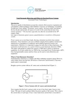
2 Gain Power-down control Single 5 V supply operation 32-lead, 5 mm x 5 mm LFCSP APPLICATIONS Differential ADC drivers Main and diversity IF sampling receivers Wideband multichannel receivers Instrumentation FUNCTIONAL BLOCK DIAGRAM POST-AMP CHANNEL AGAINDECODERCHANNEL BGAINDECODERA0A1A2A3A4B0B1B2B3B4 GNDAVCCAGNDBVCCBAD8376 IPA+IPA VCMAVCMBOPA+OPA+ENBBOPA OPA ENBAPOST-AMP IPB+IPB OPB+OPB+OPB OPB 06725-001 Figure 1. GENERAL DESCRIPTION The AD8376 is a dual channel, digitally controlled, variable gain wide bandwidth amplifier that provides precise gain control, high IP3, and low noise figure. The excellent Distortion perform-ance and high signal bandwidth make the AD8376 an excellent gain control device for a variety of receiver applications.
3 Using an advanced high speed SiGe process and incorporating proprietary Distortion cancellation techniques, the AD8376 achieves 50 dBm output IP3 at 200 MHz. The AD8376 provides a broad 24 dB gain range with 1 dB resolution. The gain of each channel is adjusted through dedicated 5-pin control interfaces and can be driven using standard TTL levels. The open-collector outputs provide a flexible interface, allowing the overall signal gain to be set by the loading impedance. Thus, the signal voltage gain is directly proportional to the load. Each channel of the AD8376 can be individually powered on by applying the appropriate logic level to the ENBA and ENBB power enable pins. The quiescent current of the AD8376 is typically 130 mA per channel.
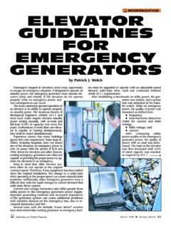
4 When powered down, the AD8376 consumes less than 5 mA and offers excellent input-to -output isolation, lower than 50 dB at 200 MHz. Fabricated on an analog devices , Inc., high speed SiGe process, the AD8376 is supplied in a compact, thermally enhanced, 5 mm 5mm 32-lead LFCSP package and operates over the temperature range of 40 C to +85 C. 40 60 50 70 90 80 100 1106555605040453530 HARMONIC Distortion (dBc), OUTPUT @ 2V p-pOIP3 (dBm), OUTPUT @ 3dBm/TONE406080100120140160180200 FREQUENCY (MHz)06725-052 OIP3HD2HD3 Figure 2. Harmonic Distortion and Output IP3 vs. Frequency AD8376 data Sheet Rev. B | Page 2 of 24 TABLE OF CONTENTS Features .. 1 Applications .. 1 Functional Block Diagram .. 1 General Description.
5 1 Revision History .. 2 Specifications .. 3 Absolute Maximum Ratings .. 5 ESD Caution .. 5 Pin Configuration and Function Descriptions .. 6 Typical Performance Characteristics .. 7 Circuit Description .. 12 Basic Structure .. 12 Applications .. 13 Basic Connections .. 13 Single-Ended-to-Differential Conversion .. 13 Broadband Operation .. 15 ADC Interfacing .. 15 Layout Considerations .. 18 Characterization Test Circuits .. 18 Evaluation Board .. 19 Outline Dimensions .. 23 Ordering Guide .. 23 REVISION HISTORY 10/13 Rev. A to Rev. B Changed ENBA, ENBB, A0 to A4, B0 to B4 Maximum Rating to + V; Table 3 .. 5 Updated Outline Dimensions .. 23 Changes to Ordering Guide .. 23 10/10 Rev. 0 to Rev. A Changes to Figure 3 and Table 4.
6 6 Changes to Figure 36 .. 14 Added Exposed Pad Notation to Outline Dimensions .. 23 8/07 Revision 0: Initial Version data Sheet AD8376 Rev. B | Page 3 of 24 SPECIFICATIONS VS = 5 V, T = 25 C, RS = RL = 150 at 140 MHz, 2 V p-p differential output, both channels enabled, unless otherwise noted. Table 1. Parameter Conditions Min Typ Max Unit DYNAMIC PERFORMANCE 3 dB Bandwidth VOUT < 2 V p-p ( dBm) 700 MHz Slew Rate 5 V/ns INPUT STAGE Pin IPA+ and Pin IPA , Pin IPB+ and Pin IPB Maximum Input Swing For linear operation (AV = 4 dB) V p-p Differential Input Resistance Differential 120 150 165 Common-Mode Input Voltage V CMRR Gain code = 00000 dB GAIN Amplifier Transconductance Gain code = 00000 S Maximum Voltage Gain Gain code = 00000 20 dB Minimum Voltage Gain Gain code 11000 4 dB Gain Step Size From gain code = 00000 to 11000 dB Gain Flatness All gain codes, 20% fractional bandwidth for fC < 200 MHz dB Gain Temperature Sensitivity Gain code = 00000 8 mdB/ C Gain Step Response For VIN = 100 mV p-p, gain code = 10100 to 00000 5 ns OUTPUT STAGE Pin OPA+ and Pin OPA , Pin OPB+ and Pin OPB Output Voltage Swing At P1dB.
7 Gain code = 00000 V p-p Output Impedance Differential 16|| k ||pF Channel Isolation Measured at differential output for differential input applied to alternate channel (referred to output) 73 dB NOISE/HARMONIC PERFORMANCE 46 MHz Gain code = 00000 Noise Figure dB Second Harmonic VOUT = 2 V p-p 92 dBc Third Harmonic VOUT = 2 V p-p 94 dBc Output IP3 2 MHz spacing, 3 dBm per tone 50 dBm Output 1 dB Compression Point dBm 70 MHz Gain code = 00000 Noise Figure dB Second Harmonic VOUT = 2 V p-p 89 dBc Third Harmonic VOUT = 2 V p-p 95 dBc Output IP3 2 MHz spacing, 3 dBm per tone 50 dBm Output 1 dB Compression Point dBm 140 MHz Gain code = 00000 Noise Figure dB Second Harmonic VOUT = 2 V p-p 87 dBc Third Harmonic VOUT = 2 V p-p 97 dBc Output IP3 2 MHz spacing.
8 3 dBm per tone 51 dBm Output 1 dB Compression Point dBm 200 MHz Gain code = 00000 Noise Figure dB Second Harmonic VOUT = 2 V p-p 82 dBc Third Harmonic VOUT = 2 V p-p 91 dBc Output IP3 2 MHz spacing, 3 dBm per tone 50 dBm Output 1 dB Compression Point dBm AD8376 data Sheet Rev. B | Page 4 of 24 Parameter Conditions Min Typ Max Unit POWER INTERFACE Supply Voltage V VCC and Output Quiescent Current with Both Channels Enabled Thermal connection made to exposed paddle under device 245 250 255 mA vs. Temperature 40 C TA +85 C 285 mA Power-Down Current, Both Channels ENBA and ENBB Low mA vs. Temperature 40 C TA +85 C 7 mA POWER-UP/GAIN CONTROL Pin A0 to Pin A4, Pin B0 to Pin B4, Pin ENBA, and Pin ENBB VIH Minimum voltage for a logic high V VIL Maximum voltage for a logic low V Logic Input Bias Current 900 nA Table 2.
9 Gain Code vs. Voltage Gain Look-Up Table 5-Bit Binary Gain Code Voltage Gain (dB) 00000 +20 00001 +19 00010 +18 00011 +17 00100 +16 00101 +15 00110 +14 00111 +13 01000 +12 01001 +11 01010 +10 01011 +9 01100 +8 5-Bit Binary Gain Code Voltage Gain (dB) 01101 +7 01110 +6 01111 +5 10000 +4 10001 +3 10010 +2 10011 +1 10100 0 10101 1 10110 2 10111 3 11000 4 >11000 4 data Sheet AD8376 Rev. B | Page 5 of 24 ABSOLUTE MAXIMUM RATINGS Table 3. Parameter Rating Supply Voltage, VPOS V ENBA, ENBB, A0 to A4, B0 to B4 V to (VPOS + V) Input Voltage, VIN+, VIN V to + V DC Common Mode VCMA, VCMB V VCMA, VCMB 6 mA Internal Power Dissipation W JA (Exposed Paddle Soldered Down) C/W JC (At Exposed Paddle) C/W Maximum Junction Temperature 140 C Operating Temperature Range 40 C to +85 C Storage Temperature Range 65 C to +150 C Stresses above those listed under Absolute Maximum Ratings may cause permanent damage to the device.
10 This is a stress rating only; functional operation of the device at these or any other conditions above those indicated in the operational section of this specification is not implied. Exposure to absolute maximum rating conditions for extended periods may affect device reliability. ESD CAUTION AD8376 data Sheet Rev. B | Page 6 of 24 PIN CONFIGURATION AND FUNCTION DESCRIPTIONS PIN 1 INDICATOR1A22A33A44 VCMANOTES1. THE EXPOSEDPAD IS INTERNALLY CONNECTEDTO GROUND. SOLDERTO A LOW IMPEDANCE GROUND +23 OPA 22 ENBA21 GNDA20 GNDB19 ENBB18 OPB 17 OPB+9B110B011 IPB+12 IPB 13 GNDB14 VCCB15 OPB+16 OPB 32A131A030 IPA+29 IPA 28 GNDA27 VCCA26 OPA+25 OPA AD8376 TOP VIEW(Not to Scale)06725-002 Figure 3. 32-Lead LFCSP Table 4.