Transcription of Universal Evaluation Board for the AD8452 - …
1 AD8452 -EVALZ User GuideUG-1180 One Technology Way P. O . Box 9106 Norwood, MA 02062-9106, Te l : Fax: Universal Evaluation Board for the AD8452 PLEASE SEE THE LAST PAGE FOR AN IMPORTANT WARNING AND LEGAL TERMS AND CONDITIONS. Rev. 0 | Page 1 of 14 FEATURES Pin accessible, standalone AD8452 Simplified operation: connect a power supply and scope and start looking at waveforms On- Board precision 5 V reference included for accurate gain measurements Factory tested Four optional control loops available but not necessary for operation; may be bypassed as desired Safe: only low power circuitry is present; no accidental power discharges ADDITIONAL EQUIPMENT NEEDED +12 V, +5 V, 5 V bench supply: Keysight E3631 or equivalent power supply with current metering and adjustable output current-limiting 50 mV diode emulation/current-limiting bias voltage Oscilloscope: Tektronix DPO7104 or multichannel equivalent DMM: 4 digit or greater Test jumpers with grabber or mini-gator clips Optional.
2 Power amplifier, Li-Ion battery, current transducer (low resistance shunt) DOCUMENTS NEEDED AD8452 data sheet GENERAL DESCRIPTION The AD8452 -EVALZ is a platform for the AD8452 , designed for investigation of the AD8452 analog and pulse-width modulation (PWM) features and performance without the added complica-tions of a driver and/or switch mode power supply (SMPS) design. For convenience, a precision 5 V reference IC and four trim pots are built in to the Evaluation Board , for driving the battery current and voltage ISET and VSET inputs. All device pins are accessible with test loops or probe landings. At the same time, the AD8452 -EVALZ has the flexibility to interface and drive a typical half bridge inductor input SMPS with output levels in the 1 A to 15 A range.
3 SMPS and associated components are specified and sourced by the user. The AD8452 is intended for use as the core controller for commercial battery test and formation systems. Its advanced miniaturization and extraordinarily high level of analog precision meet the challenge of mass production of high energy density storage lithium ion packs for transportation and energy storage in homes. Figure 1 is a photograph of the AD8452 -EVALZ. When working with the Evaluation Board , consult the AD8452 data sheet for a detailed device Theory of Operation and for additional information in conjunction with this user guide. Evaluation Board PHOTOGRAPH 16188-001 Figure 1. UG-1180 AD8452 -EVALZ User Guide Rev. 0 | Page 2 of 14 TABLE OF CONTENTS Features.
4 1 Additional Equipment Needed .. 1 Documents Needed .. 1 General Description .. 1 Evaluation Board Photograph .. 1 Revision History .. 2 Overview of the 3 Evaluation Board Hardware ..4 Te s t Evaluation Board Schematics and Artwork ..9 Ordering Information .. 13 Bill of Materials .. 13 Related Links .. 14 REVISION HISTORY 10/2017 Revision 0: Initial Version AD8452 -EVALZ User Guide UG-1180 Rev. 0 | Page 3 of 14 OVERVIEW OF THE AD8452 The AD8452 is a front-end controller for battery test or formation systems. It is a 48-lead device in a 7 mm 7 mm LQFP package, comprised of a high performance analog section and PWM. A block diagram is shown in Figure 2. Refer to the AD8452 data sheet for a full description.
5 16188-00287654329121110 ISVPVREG = 5 VISVN3328272534 AVEE126353829 ISREFHVREFISREFLSISREFLIVE1 ISMEAIVE0 ISETVINTAGNDCLNAVCCCLPVVE1 VINTVVE0 VVP0 VSETCLVSETBAVCC37 BVREFHBVPSBVREFLBVPBVNSBVREFLSENBVMEABVN MODE500 100k BATTERYCURRENTSENSE IAG = 66 SSMODE_B3132 AVCC300 60k AVEEAVEE36 DHDLVINCLVTSCFGFAULTVREGDTSSFREQDGNDSYNC 1M 1M SSCLSS1 80k 200k SS 200k SCFGSCFGCONFIGDETECT304V1 SYNCSYNC DETECTAVEEAVCCBATTERYVOLTAGESENSE DAG = 'CLFLGCLFLGSYNCOSCILLATORVREGUVLOTSDBAND GAPMODE_B5 A+/ CURRENT LIMITAND DIODEEMULATIONVSETBUFFERMODE_BCV LOOPFILTERAMPLIFIERVCTRL-COMPIDMAX11 AISCFG11 AVBG = A20 A20 AVFREQ= Figure 2. Detailed Block Diagram of the AD8452 Showing the High Performance Analog Section and the PWM Section UG-1180 AD8452 -EVALZ User Guide Rev.
6 0 | Page 4 of 14 Evaluation Board HARDWARE Figure 3 is a system level block diagram comprising three functional system level block diagrams, an AD8452 -EVALZ block diagram, including its user adjustable current and voltage control compensation matrix, and a simple precision reference (an ADR4550) for driving current and voltage inputs throughout the PWM conversion process to the outputs DH and DL. The balance of the large signal system in Figure 3 is user supplied and consists of the metal-oxide semiconductor field effect transistor (MOSFET) driver and user supplied SMPS, an inductor-capacitor (L-C) output filter with a current limiting resistor (RCL), and a current sense shunt. A description of some simple experiments with the AD8452 follows.
7 The AD8452 -EVALZ can be connected as the analog and PWM small signal digital controller of a complete battery formation system, allowing users to explore the AD8452 functions in detail, with an emulated system input/output (I/O) provided. The Board can also be operated as a channel controller for a power channel custom designed to the unique needs and requirements of the user. For more system information on system applications, including communication links, see the AD8452 UG-1181. COMPENSATIONMATRIXDDDDDDCCCADR4550(+5VR) +5 VROUTPUTSWITCHES(USERSUPPLIED)LLPFRCLLEV ELSHIFTERADI EVAL-ADUMX3223 EBZ(TYPICAL)CLPFBATTERY FORMATION SYSTEM-LEVEL CHANNELCONTROLLERBATTERYCURRENTSENSESHUN TISVPISVNBVPBVNMODESWITCHES(3)BATTERYCUR RENT(IBAT)AVEECONSTANT CURRENTLOOP FILTER AMPLIFIER1 VINTBUFFERVSETBUFVSETISETCDCDCDVINTISMEA VVE1 VVE0 VVP0AD8452 IBATC = CHARGED = DISCHARGECONSTANT VOLTAGELOOP FILTER ANDDIODEEMULATIONCHARGEDISCHARGE1 +5 VRVBAT+5 VREXTERNAL DC TO DCPOWER CONVERTERAND BATTERY CIRCUITRY(USER SUPPLIED) AD8452 -EVALZBVMEADAIAC16188-003 Figure 3.
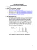
8 Block Diagram Showing the AD8452 and External Circuitry Boundaries AD8452 -EVALZ User Guide UG-1180 Rev. 0 | Page 5 of 14 TEST SETUP +5V 5V+12 VGND4-CHANNEL SCOPEPOWER SUPPLY 50mV BIAS SUPPLY16188-004 Figure 4. Typical Setup for the AD8452 -EVALZ Bench Test Jumper Positions There are five 2-pin jumpers installed on the Evaluation Board (see Figure 5). Table 1 shows their location and function. Table 1. Jumper Locations and Functions Location Function P3 VSET input. P4 ISET input.
9 CONN_VIN Connects AVCC to VIN. P1-1 and P1-2 Shorts ISVP and ISVN to keep instrumentation amplifier voltage input at 0 V. P1-3 and P1-4 Inserted for Charge Mode Te s t Shorts BVP and BVN to keep difference amplifier input at 0 V. P1-3 and P1-4 Removed for Discharge Mode Test Mimics the state of battery conditions during a discharge cycle by simulating a fully charged battery. The lower value VSET voltage establishes the withdrawal current from the higher voltage battery. DC Testing Board Setup and Power Supply Currents With the Evaluation Board set up as shown in Figure 4, the power supply currents are those shown in Table 2.
10 The test loops in Figure 4 are color coded: black is for ground; red for positive voltages; orange for negative voltages; green for 5 V logic supplies; and purple corresponds to the signal test points shown in the schematic (see Figure 8). When power is applied to the Evaluation Board , there can be a momentary current surge, especially if the filter capacitors are not recently charged. This behavior is normal, and the supply currents settle to their typical values in a few seconds. It is strongly recommended that the power supply used for experimenting feature current metering and current-limiting. Table 2. Power Supply Load Currents by Supply Pin Supply (V) Power Supply Current Limiting (Optional) (mA) Load Current (Typical) AVCC (+12) 20 +9 mA 5 10 4 mA +5 5 +1 A UG-1180 AD8452 -EVALZ User Guide Rev.