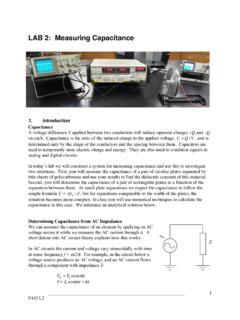
LAB 2: Measuring Capacitance
ideal resistor and capacitor in series. The capacitance is due to the parallel plates (plus stray capacitance from other parts of the circuit). The resistance includes the resistance of the wires and the output impedance of the AC voltage source. If there were no resistive component to the circuit, then the ratio of the current to voltage would
Download LAB 2: Measuring Capacitance

Information
Domain:
Source:
Link to this page:
Documents from same domain

GEL 120 - PHYSICAL GEOLOGY LABORATORY
d32ogoqmya1dw8.cloudfront.netgel 120 – physical geology laboratory fall semester 2011 natural sciences/health & pe department mathematics and sciences division ... your laboratory manual to class.

GEOL 1301 – NATURAL HAZARDS AND DISASTERS
d32ogoqmya1dw8.cloudfront.netGEOL 1305 Syllabus – Fall 2009 – Page 3 Late assignments placed in the instructorʼs mailbox in the campus administration area MUST have the date of receipt stamped on them by the administrative assistant in the mailroom.

Graphing Sunspot Numbers
d32ogoqmya1dw8.cloudfront.net6. Estimate the dominant period of the sunspot signal. Explain and show your calculations below. 7. During the next 15 years about when do you expect the solar activity to be high
Berquist Thomas Nelson Community College
d32ogoqmya1dw8.cloudfront.netPete Berquist Thomas Nelson Community College Most students enrolled in my geology courses may never take a science class ever again, yet I find it likely …

Earth Science Introduction
d32ogoqmya1dw8.cloudfront.netGLOBE® 2003 Introduction - 6 Earth System Science Components of the Earth System The GLOBE program has students take measure-ments of many parts of the Earth’s systems. The table below indicates where the GLOBE investiga-tions lie with the components of the Earth system.

INTRODUCTION TO EARTH SCIENCE
d32ogoqmya1dw8.cloudfront.netObjectives: Introduction to Earth Science will expose you, the student, to the principles that underlie our understanding of how and why the Earth evolves. You …
COURSE INFORMATION Fall 2016 GEOL 1030-1 INTRO TO …
d32ogoqmya1dw8.cloudfront.netGEOL 1030-1 INTRO TO EARTH SCIENCE-LECTURE --- BASIC INFO --- LECTURE TIMES AND LOCATION: MWF 9:10a-10:05a in 452 KOM. ... If you miss a lecture, obtain notes and/or handouts from a student who was there. Absences for university sponsored events (e.g., athletics and

Syllabus for Earth Science
d32ogoqmya1dw8.cloudfront.net4 credits (3 lecture hours, 2 lab hours) Instructor: Joy Branlund ... You will be able to use YOUR notes (but no book, photocopied, borrowed or shared notes) for the Prep Checks. Homework (some completed in-class) ... Syllabus for Earth Science ...

September 2016 Newsletter Volume 2 Number 1
d32ogoqmya1dw8.cloudfront.net1 September 2016 Newsletter Volume 2 Number 1 TED’s President olumn By Jeff Thomas Dear TED Members: Let me start by welcoming all new and returning TED members, and I …

Overview of the Research Methods Used by Geoscience ...
d32ogoqmya1dw8.cloudfront.netSolutions • Establish and communicate norms for geoscience education research • GSA session to share methods and techniques Purpose • Provide overview of education research and framework to
Related documents

RLC Resonant Circuits - University of Cambridge
mlg.eng.cam.ac.ukFor the simple parallel RLC circuit shown in gure 5 this is just equal to the rms supply voltage but for the series RLC circuit it is given by a potential divider rule. Therefore, for series circuits it is in general simpler to calculate the max energy stored by considering the inductor and in parallel circuits by considering the capacitor.
Intro to Electricity
engineering.nyu.eduSeries Connection of Cells • Each cell provides 1.5 V • Two cells connected one after another, ... circuits. •Henceforth, the conductors that exhibit the property of resisting current flow are ... the resistive material and tap off the desired resistance.
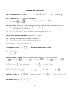
ELECTRONIC FORMULAS - TSCM
tscm.com2 (for series circuit ) Z ’ RX R 2%X (for R and X in parallel ) Q ’ X L R or X C R 2-7.1 ELECTRONIC FORMULAS Ohm's Law Formulas for D-C Circuits. Ohm's Law Formulas for A-C Circuits and Power Factor. In the above formulas 1 is the angle of lead or lag between current and voltage and cos 1 = P/EI = power factor or pf.
Series and Parallel Resistive Circuits - Mercer University
physics.mercer.eduSeries & Parallel Resistive Circuits 5 Series Combinations In this set of experiments, the total resistance of resistors in a series combination will be measured. In addition, measurements will be made to check the validity of the as-sumptions used to derive the theoretical expression for the total resistance of a series combination. 1.
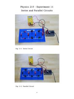
Physics 215 - Experiment 11 Series and Parallel Circuits
www.phy.olemiss.eduSeries and Parallel Circuits 44 + V - 2 The third type of circuit you will construct is a ccombination circuit (Fig. 11-3 and Fig. 11-6). Resistive elements are not connected in series or parallel. To analyze this type of circuit, it should first be simplified (reduced to an equivalent resistor, Req). R Fig. 11-6: Combination Circuit Schematic ...
`Ohm’s Law III -- Resistors in Series and Parallel
www.phys.utk.eduOhm’s Law III—Resistors in Series and Parallel V RRR 2 1 2 3 E V 1 V 3 V T I 1 I I T 2 I 3 Figure 1. Three resistors R1, R2, and R3 connected in series. The voltage drop across the battery VT will be the total sum of the individual drops across each of the 3 resistors, and

Chapter 12 Alternating-Current Circuits
web.mit.edu12.2 Simple AC circuits Before examining the driven RLC circuit, let’s first consider the simple cases where only one circuit element (a resistor, an inductor or a capacitor) is connected to a sinusoidal voltage source. 12.2.1 Purely Resistive load Consider a purely resistive circuit with a resistor connected to an AC generator, as shown
AC Electrical Circuit Analysis
www2.mvcc.eduin a circuit, as well as between currents or resistive/reactive values. Many of the topics in this text will echo your studies in DC circuit analysis, such as Ohm's law, Kirchhoff's voltage and current laws, series-parallel analysis, nodal analysis, and the like.
LM1875 20W Audio Power Amplifier datasheet (Rev. A)
www.ti.com• Protection for AC and DC Short Circuits to supplies, over 30 watts of power may be delivered. ... least 1Ω) should be placed in series with the output of the LM1875. A method commonly employed to protect amplifiers from low impedances at high frequencies is to couple to the load through a 10Ωresistor in parallel with a 5 μH inductor.
Chapter 7 Direct-Current Circuits
web.mit.edu7.3 Resistors in Series and in Parallel The two resistors R1 and R2 in Figure 7.3.1 are connected in series to a voltage source∆V. By current conservation, the same current I is flowing through each resistor. Figure 7.3.1 (a) Resistors in series. (b) Equivalent circuit.
Related search queries
Circuits, Parallel, Series, Series circuits, Parallel circuits, Resistive, ELECTRONIC FORMULAS, Formulas, Series and Parallel Resistive Circuits, Parallel Resistive Circuits, Physics 215 - Experiment 11 Series and Parallel Circuits, Series and Parallel Circuits, Series and Parallel, AC Electrical Circuit Analysis, Chapter 7 Direct-Current Circuits