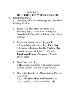
LECTURE 34 HIGH FREQUENCY TRANSFORMER
ripple and input ripple current, and is an important concept in control loop design. In a single-ended power circuit such as the forward converter, the power switch, the transformer, and the output rectifier all operate at the switching frequency and there is no confusion. The transformer frequency and the switching frequency are the same. This is
Download LECTURE 34 HIGH FREQUENCY TRANSFORMER

Information
Domain:
Source:
Link to this page:
Documents from same domain
LECTURE 18 Switches and Switch Stress: The …
www.engr.colostate.edusemiconductor switch as opposed to mechanical switches multi- ... the other static state depends both on the switch device and the circuit.

B. Empirical Differences in CCM versus DCM …
www.engr.colostate.edu1 Lecture 37 Introducing Discontinuous Conduction Mode A. Discontinuous Conduction Mode (DCM) versus Continuous Conduction Mode (CCM): Circuit Topology Transitions

The Customer Value Proposition
www.engr.colostate.eduThe Customer Value Proposition Differentiation through the Eyes of Your Customer Pamela Hudadoff Dedicated to making expert marketing techniques more accessible
ECE562 Power Electronics Schedule and Grading
www.engr.colostate.edupower supplies on a chip or on a board in any electronic system requiring powered DC levels different from the general DC system bus. Typically this is 6-12 additional DC levels.

Types of Flowmeters - Walter Scott, Jr. College of Engineering
www.engr.colostate.edu5" " " Figure"1."Example"of"an"Orifice"Plate;"(Engineering"ToolBox,"2010)" • Flow"Nozzles" AFlow"Nozzle"is"very"similar"to"an"orifice"plate,"the"main"difference"is ...
New Lecture 20 - Walter Scott, Jr. College of Engineering
www.engr.colostate.eduand the MOSFET is the insulated gate bipolar transistor (IGBT). This device was invented to capture the two separate advantages of each the bipolar and the MOSFET transistor in one device.
Lecture 3 - Data Converters
www.engr.colostate.eduLecture 3 - Data Converters James Barnes (James.Barnes@colostate.edu) Spring 2014. Lab2 Info Lab2 Info Lissajou Figures Support Files Update Introduction to ADCs Quantization Noise and Effective Number of Bits Oversampling ADC Noise Filtering and Decimation
20 The Laplace Transform
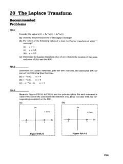
www.engr.colostate.eduThe Laplace Transform / Problems P20-3 P20.6 (a) From the expression for the Laplace transform of x(t), derive the fact that the Laplace transform of x(t) is the Fourier x(t) weighted by an exponential. (b) Derive the expression for the inverse Laplace transform using the Fourier transform …
United States Army Corps of Engineers Engineering …
www.engr.colostate.edu14 Riprap Characteristics •Gradation – Should be determined from a quarry test AND an in-place field test – Upper and lower limits typically specified
MathCAD Tutorial - Walter Scott, Jr. College of Engineering
www.engr.colostate.edu2 The first time I heard about the MathCAD software is in my analog circuit design class. Dr. Gary Robison suggested that I should apply a new tool such as MathCAD or MatLab to solve
Related documents

Abstract - arXiv
arxiv.orgthe bottom branch classifies the current search patch. As shown in Figure1, we separate the transformer encoder and decoder into two branches within such a general Siamese-like structure. In the top branch, a set of template patches are fed to the transformer encoder to generate high-quality encoded features. In the bottom branch, the search ...

Power Transformer Protection - ABB
library.e.abb.comGround fault current in a solidly grounded Y-connected winding. Ground fault current in a high impedance grounded Y-connected winding. Theoretical inrush currentlm. Recorded inrush current for a 60 MV A transformer 140/40/6.6 kV. connected YNyd. Operating time. Through faun restraint. Magnetizing current at overexitation.

Power Transformer Fundamentals: Design and Manufacturing
r5.ieee.orgGenerator Step-Up Auto-Transformer Step-Down Pads Transformer Transformer 115/10 or 20 kV 500/230 230/13.8 132 345/161 161 161 230/115 132 230 230/132 115 345 69 500 34 With and without LTC Specification vs. Design

Back to the Basics Current Testing - Valence Electrical
relaytraining.comBack to the Basics – Current Transformer (CT) Testing As test equipment becomes more sophisticated with better features and accuracy, we risk turning our field personnel into test set operators instead of skilled field service technicians. A test set operator connects the leads, pushes the buttons, and records the

Vibration and Shock tests on a typical Current Transformer …
www.eleq.comThe test object is a typical example of a Current Transformer Set. ELEQ Steenwijk B.V. produces a range of transformers differentiating in weight and dimensions. The selected Current Transformer Set is of average weight and has a relative high "height to width ratio", which is expected to be worst case for vibration and shock testing.
Understanding Time Current Curves - Maverick Technologies
www.mavtechglobal.comThe transformer inrush current is also plotted as a single point on the TCC diagram. Again, as part of the initial design, the transformer inrush current must be to the left of the transformer primary fuse curve otherwise the fuse will open when the transformer is energized. These differences in the unbalanced and 100% damage curves can
Transformer asics Information Guide - Motion Labs
www.motionlabs.comelectric energy from one set of windings (primary) to another set of windings (secondary). In addition to the “basic” transformer design, there are other specialty configurations, such as, uck/oost, which are described in Types & Uses. While the voltage and current usually change (from primary to
Components and Methods for Current Measurement
www.vishay.comFig. 1 - Ideal current transformer circuit Fig. 2 - Current transformer loss components Rogowski Coil The Rogowski coil (Fig. 3) is similar to a current transformer in that a voltage is induced into a secondary coil that is propo rtiona l to the …