PM0075 Programming manual - STMicroelectronics
ICP (in-circuit programming): ICP is the ability to program the Flash memory of a microcontroller using the JTAG protocol, the SWD protocol or the boot loader while the device is mounted on the user application board. I-Code: this bus connects the Instruction bus of the Cortex-M3 core to the Flash instruction interface.
Download PM0075 Programming manual - STMicroelectronics

Information
Domain:
Source:
Link to this page:
Documents from same domain

Low-power dual operational amplifier - st.com
www.st.comFebruary 2016 DocID2471 Rev 17 1/24 This is information on a product in full production. www.st.com LM2904, LM2904A Low-power dual operational amplifier

AN3128 Application note - st.com
www.st.comJune 2011 Doc ID 16918 Rev 5 1/105 AN3128 Application note STM32 embedded graphic objects/touchscreen library Introduction This library is a firmware package which contains a collection of routines, data structures,

AN4767 Application note - st.com
www.st.comDocID028380 Rev 2 7/16 AN4767 Dual bank use cases 15 With dual bank, all the manipulation with the other bank is just another task of the main program.

AN3155 Application note - st.com
www.st.comOctober 2016 DocID17066 Rev 7 1/37 1 AN3155 Application note USART protocol used in the STM32 bootloader Introduction This application note describes the USART protocol used in the STM32 microcontroller

USB Power Delivery and Type-C - st.com
www.st.comUSB Type -C Overview USB Power Delivery specification introduces USB Type-C receptacle, plug and cable; they provide a smaller, thinner and more robust alternative to existing USB interconnect.

Datasheet - L78 - Positive voltage regulator ICs - …
www.st.comTO- 2 2 0 TO-2 2 0 F P DPAK D² PAK Features • Output current up to 1.5 A • Output voltages of 5; 6; 8; 8.5; 9; 12; 15; 18; 24 V • Thermal overload protection

AN2867 Application note - st.com
www.st.comMay 2017 DocID15287 Rev 11 1/43 1 AN2867 Application note Oscillator design guide for STM8AF/AL/S and STM32 microcontrollers Introduction Many designers know oscillators based on Pierce-Gate topology (hereinafter referred to as

AN4776 Application note - st.com
www.st.comMay 2017 DocID028459 Rev 2 1/73 1 AN4776 Application note General-purpose timer cookbook Introduction The timer peripheral is part of …

120-volt, 100-watt, DMOS audio amplifier with mute …
www.st.comSeptember 2010 Doc ID 6744 Rev 8 1/21 21 TDA7293 120-volt, 100-watt, DMOS audio amplifier with mute and standby Features Multipower BCD technology Very high operating voltage range (±50 V)

Electronic transformer for a 12V halogen lamp - …
www.st.comAPPLICATION NOTE AN528/0999 1/4 ELECTRONIC TRANSFORMER FOR A 12V HALOGEN LAMP by P. Fichera, R. Scollo 1. INTRODUCTION Lighting that uses halogen lamps is commonly found
Related documents

Future Technology Devices International Ltd FT231X
www.ftdichip.comThe FT231X is a USB to serial UART interface with full modem control and ... Integrated power -on-reset circuit. Fully integrated AVCC supply filtering - no ... For a description of each function please refer to Section 4.

2-Mbit serial I²C bus EEPROM - STMicroelectronics
www.st.com(see Operating conditions in Section 8: DC and AC parameters). 2.6.3 Device reset In order to prevent inadvertent write operations during power-up, a power-on-reset (POR) circuit is included. At power-up, the device does not respond to any instruction until VCC has reached the internal reset threshold voltage.

AD5522 (Rev. F) - Analog Devices
www.analog.comQuad Parametric Measurement Unit with Integrated 16-Bit Level Setting DACs Data Sheet AD5522 Rev. F Document Feedback Information furnished by Analog Devices is believed to be accurate and reliable.

cp2102rev1 0 - SparkFun Electronics
www.sparkfun.comUSB to RS-232 serial adapter Supply Voltage Self-powered: 3.0 to 3.6 V USB bus powered: 4.0 to 5.25 V Package Lead free 28-pin MLP (5 x 5 mm) Ordering Part Number Temperature Range: –40 to +85 °C Figure 1. Example System Diagram CP2102 3.3 V Voltage Regulator 48 MHz Oscillator IN OUT SUSPEND SUSPEND 11 12 REGIN 7 GND 3 RST 9 D+ 4 D-5 8 UART ...
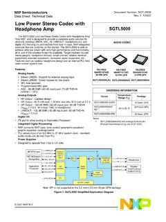
SGTL5000, Low Power Stereo Codec with Headphone Amp - …
www.nxp.com18 27 CTRL_DATA Digital I2C Mode: Serial Data (SDA); SPI Mode: Serial Data Input (MOSI) 19 29 CTRL_CLK Digital I2C Mode: Serial Clock (SCL); SPI Mode: Serial Clock (SCK) 20 30 VDDD Digital Digital voltage For new designs, connect VDDD to an external voltage source and to a 0.1 F capacitor to GND. - 31 CTRL_ADR0_CS Digital I2C Mode: I2C Address

Platform Management FRU Information Storage …
www.intel.comFeb 02, 2013 · Platform Management FRU Information Storage Definition 2 Product Info Area This area is present if the FRU itself is a separate product. This is typically seen when the FRU is an add-in card, sub-assembly, or a power supply from a
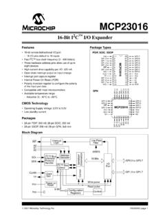
MCP23016 16-Bit I2C I/O Expander - Microchip Technology
ww1.microchip.comDec 08, 2006 · GP0.7 28 25 I/O TTL D7 digital input/output for GP0 SCL 14 11 I ST Serial clock input SDA 15 12 I/O ST Serial data I/O INT 6 3 O OD Interrupt output A0 16 13 I ST Address input 1 A1 17 14 I ST Address input 2 A2 18 15 I ST Address input 3 VSS 1, 8, 19 5, 16, 26 P — Ground reference for logic and I/O pins

AD7998/AD7997 8-Channel, 10- and 12-Bit ADCs with I2C ...
www.analog.com2. I2C-compatible serial interface with pin-selectable addresses. Two AD7997/AD7998 versions allow five AD7997/AD7998 devices to be connected to the same serial bus. 3. The parts feature automatic shutdown while not converting to maximize power efficiency. Current consumption is 1 µA max when in shutdown mode at 3V. 4.

PCA9306 - Dual Bidirectional I2C-bus and SMBus Voltage ...
www.onsemi.comPCA9306 www.onsemi.com 2 Function Description The PCA9306 is a dual bidirectional I2C−bus and SMBus voltage−level translator with an enable (EN) input, and is operational from 1.0 V to 3.6 V (Vref(1)) and 1.8 V to 5.5 V (Vbias(ref)(2)). The …

ENGLISH - Rinnai
www.rinnai.ussteps in section 3(A) (next page). • For all other Rinnai Tankless Water Heaters, see section 3(B). Replace and tighten the four (4) screws on the water heater cover. Plug in the water heater power cord. Turn on the water heater by pressing the On/Off button on the water heater controller.