Simulating Verilog RTL using Synopsys VCS
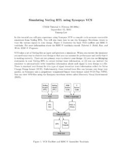
Sep 12, 2010 · Simulating Verilog RTL using Synopsys VCS CS250 Tutorial 4 (Version 091209a) September 12, 2010 Yunsup Lee In this tutorial you will gain experience using Synopsys VCS to compile cycle-accurate executable simulators from Verilog RTL. You will also learn how to use the Synopsys Waveform viewer to trace the various signals in your design.
Download Simulating Verilog RTL using Synopsys VCS

Information
Domain:
Source:
Link to this page:
Documents from same domain
Diodes and Transistors
inst.eecs.berkeley.eduDiodes and Transistors 1. ... basic semiconductor physics. We won’t discuss the details because the point of this ... switch. Below the specified ...
HSPICE Tutorial - University of California, Berkeley
inst.eecs.berkeley.eduHSPICE Tutorial Contents 1 Introduction 1 ... ee105 spice tutorial example 1 - simple rc circuit in the Results Browser and double-clicking vs and vo to plot them in the graph. You may have been able to guess from the netlist, but you’ll see that vsis a …
Introduction to LabVIEW - University of California, …
inst.eecs.berkeley.eduIntroduction to LabVIEW 1. Introduction Welcome to the LabVIEW component of EE100! This lab is just a simple introduction to the graphical circuit simulation ...
Introduction to LabVIEW For Use in Embedded …
inst.eecs.berkeley.eduUC Berkeley EE249 Hugo.Andrade@ni.com Introduction to LabVIEW For Use in Embedded System Development
EE105 –Fall 2015 Microelectronic Devices and Circuits
inst.eecs.berkeley.eduSummary of MOS Single-Transistor Amplifiers MOS Common Source Common Source with Deg. Common Drain Common Gate Ri ∞ ∞ ∞ Small Ro Large Very Large Small Large
Introduction to Digital Systems - University of …
inst.eecs.berkeley.eduDepartment of EECS EE100/42-43 Spring 2007 Rev. 1 Introduction to Digital Systems 0. Acknowledgments Many thanks to Prof. Bernhard Boser and National Instruments for funding this project in the
EE126: Probability and Random Processes - Lecture 1 ...
inst.eecs.berkeley.eduprobability 4 The probabilities summed over all of the base outcomes always equals 1 Example: Toss a fair coin twice 1 Base outcomes are HH,HT,TH,TT 2 This covers all the possibilities. M.E. 3 Each of these outcomes is equally likely 4 Assign each outcome a probability of 0:25. The list (set) of base outcomes is called the Sample Space.
EECS 126 Probability and Random Processes: Course Syllabus ...
inst.eecs.berkeley.eduDescription: Probability is a mathematical discipline that allows one to reason about uncertainty: it helps us to predict uncertain events, to make better decisions under uncertainty, and to design and build systems. Throughout the course, we will teach you the fundamental ideas of probability and random processes along with the labs.
3-Phase Brushless DC Motor Pre-Driver
inst.eecs.berkeley.eduDescription The A4931 is a complete 3-phase brushless DC motor pre-driver . The device is capable of driving a wide range of N-channel power MOSFETs and can support motor supply voltages up to
DS -V I G - EECS Instructional Support Group Home Page
inst.eecs.berkeley.eduG D S I D I G-V DS + + V G S _ NMOS I-V CHARACTERISTIC • Since the transistor is a 3-terminal device, there is no single I-V characteristic. • Note that because of the gate insulator, I G = 0 A. • We typically define the MOS I-V characteristic as I D vs. V DS for a fixed V GS. • 3 modes of operation
Related documents

Digital Design - Electricals 4 You
e4uhu.comhas migrated to HDLs (e.g., Verilog) to describe the functionality of a design and to serve as the basis for documenting, simulating, testing, and synthesizing the hardware imple-mentation of the design in a standard cell‐based ASIC or an FPGA. The utility of a schematic depends on the careful, detailed documentation of a carefully constructed

CADENCE TUTORIAL
ashrafi.sdsu.eduThere are two approaches to doing this. We can either use the Verilog-XL compiler or use NCVERILOG/NCSIM. Chapter 2 talked about using Verilog-XL for carrying out RTL simulation. The same procedure could be used for simulating the netlist file. However, we will have to include TSMC 0.13um standard cell library files tcb013ghp.vand tpd013n2.v

Quartus II Testbench Tutorial - University of Washington
class.ece.uw.eduVerilog code that you want to test and its testbench. If you left the default settings for modelsim’s working directory you will probably have to browse up a few folders to find the file you want (in this case mux.v). Once you have selected the file click Compile, then …

Tutorial for VCS - Washington University in St. Louis
classes.engineering.wustl.eduSTEP 3: Getting started with Verilog • Creating a new folder (better if you have all the files for a project in a specific folder). • Enter into this new folder and start writing your Verilog script in a new file (.v file). Example code for modeling an counter is here • In addition to model code, Test Bench script has to be given in order

Simulating Verilog RTL using Synopsys VCS
inst.eecs.berkeley.eduSep 25, 2009 · Simulating Verilog RTL using Synopsys VCS CS250 Tutorial 4 (Version 092509a) September 25, 2009 Yunsup Lee In this tutorial you will gain experience using Synopsys VCS to compile cycle-accurate executable simulators from Verilog RTL. You will also learn how to use the Synopsys Waveform viewer to trace the various signals in your design.

Cadence AMS Simulator User Guide
picture.iczhiku.comVerilog-AMS Language Reference Manual. Available from Open Verilog International. Verilog-XL Reference Application notes are available from the SourceLink system provided by Customer Support. Typographic and Syntax Conventions Special typographical conventions are used to distinguish certain kinds of text in this document.

Verilator - Veripool
www.veripool.orgVerilog-XL/NC-Verilog, or Synopsys VCS. Verilator reads the specified SystemVerilog code, lints it, optionally adds coverage and waveform tracing support, and compiles the design into a source level multithreaded C++ or SystemC “model”. The resulting model’s C++ or SystemC code is output as .cpp and .h files.