Transcription of MPC5121e Serial Peripheral Interface (SPI)
1 Freescale SemiconductorApplication NoteDocument Number: AN3904 Rev. 0, 08/2009 Contents Freescale Semiconductor, Inc., 2009. All rights purpose of this application note is to describe the Serial Peripheral Interface bus controller (SPI) implemented on Freescale s MPC5121e microcontroller. It describes how to configure and use the programmable Serial controller (PSC) and PSC centralized FIFO controller (FIFOC) in all supported SPI objective of this application note is to describe the necessary steps needed to initialize and configure PSC in the SPI mode at all supported of the SPIThe Serial Peripheral Interface (SPI) protocol is asynchronous Serial data standard, primarily used to allow a microprocessor to communicate with other microprocessors or ICs such as memories, liquid crystal 1 Introduction.
2 Of the SPI.. 12 Description of the SPI module .. module in MPC5121e .. Peripheral Interface register list .. description and connection scheme .. 63 Initialization .. muxing .. bus .. frequency .. polling, interrupts, and DMA .. and FIFOC initialization.. initialization .. memory access .. 174 Modes of operation .. configuration .. mode .. mode .. mode .. mode.. 325 References .. 36 MPC5121e Serial Peripheral Interface (SPI)by: Pavel Boh ikRo nov Czech System CenterCzech Republic MPC5121e Serial Peripheral Interface (SPI), Rev. 0 Description of the SPI moduleFreescale Semiconductor2diodes (LCD), analog-to-digital converter subsystems, SPI is a very simple synchronous Serial data, master/slave protocol based on four lines: Clock line (SCLK) Serial output (MOSI) Serial input (MISO) Slave select (SS)Every SPI system consists of one master and one or more slaves, where a master initiates the communication by asserting the SS line.
3 When a slave device is selected, the master starts clocking out the data through the MOSI line to the selected slave device. The master sends and receives one bit for every clock edge. One byte can be exchanged in eight clock cycles. The master finishes communication by de-asserting the SS SPI is a primitive protocol without an acknowledgement mechanism for checking received or sent data. For safe communication, a flow control has to be implemented in the communications protocol on s a higher of the SPI module in MPC5121eThe MPC5121e PSC module in SPI mode is capable of master and slave mode as well.
4 The MPC5121e has a centralized FIFO controller that contains data to be transmitted plus the received data for all twelve PSC modules. FIFO is divided into twenty-four slices. For each PSC module, one Tx and one Rx FIFO space is available. The size of each memory slice is fully user-programmable, depending on the free FIFO space. The FIFO slice is able to allocate maximum available memory but the user has to prevent overlay of the individual slices in the memory. The available memory space for all slices together is 32b 1024 (4 KB).Description of the SPI moduleMPC5121e Serial Peripheral Interface (SPI), Rev.
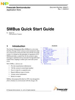
5 0 Freescale Semiconductor3 Figure 1. MPC5121e PSC and FIFOC module system interconnectionThe PSC requests new data if the Tx shift register is empty or writes Rx data to FIFOC if the Rx shift register is full. This communication is independent of external interrupt or request signals. To make sure the transfer is successful and avoid an overrun/underrun event, both transceiver and receiver must be always enabled and the core/DMA must make sure that the data slices or Tx or Rx shift registers never become Peripheral Interface register listThe PSC and FIFOC available in the MPC5121e use these registers for self-configuration and for communication with the connected device.
6 The register address is calculated as the base address for the relevant PSC plus the offset value. Table 1 shows the register list related to the PSC and Table 2 shows the register list related to the further information and detail on these registers see these chapters in Freescale document MPC5121 ERM, MPC5121e Microcontroller Reference Manual: Chapter 30, Programmable Serial controller Chapter 31, PSC Centralized FIFO controller InterruptcontrollerDMA2engineCoreInterru ptcontrollogicIPS busMemoryinterfacelogicInterface control logicConfigurationregisterFIFOCI nternal Memory 4 KBPSC0 Tx FIFO slicePSC0 Rx FIFO slicePSC1 Tx FIFO slicePSC1 Rx FIFO slicePSC9 Tx FIFO slicePSC9 Rx FIFO interfaceInternal clock sourceExternalInterruptcontrollogicInter nalchannelcontrollogicSerialcommunicatio nschannelProgrammableTx/Rx clockgenerationclock sourceSCLKSSMOSIMISOPSC Serial Peripheral Interface (SPI), Rev.
7 0 Description of the SPI moduleFreescale Semiconductor4 Table 1. Register list PSCD ressRegister NameDescriptionBase Address + 00 Mode Register 1 (MR1)Controls configurationBase Address + 00 Mode Register 2 (MR2)Controls configurationBase Address + 04 Status Register (SR)Status of PSCBase Address + 04 Clock Select Register (CSR)DefaultBase Address + 08 Command Register (CR)Provides commands to the PSCBase Address + 0 CRx Buffer Register (RB)Reads data directly from the Rx shift registerBase Address + 0 CTx Buffer Register (TB)Writes data directly from the Tx shift registerBase Address + 10 Input Port Change Register (IPCR)
8 DefaultBase Address + 10 Auxiliary Control Register (ACR)DefaultBase Address + 14 Interrupt Status Register (ISR)Status for all potential interrupt sourcesBase Address + 14 Interrupt Mask Register (IMR)Selects corresponding bits in the ISR that cause an interruptBase Address + 18 Counter Timer Upper Register (CTUR) Together with CTLR affects delay after transferBase Address + 1 CCounter Timer Lower Register (CTLR) Together with CTUR affects delay after transferBase Address + 20 Codec Clock Register (CCR)Define DSCKLL delay and SPI baud rateBase Address + 24AC97 Slots Register (AC97 Slots)DefaultBase Address + 28AC97 Command Register (AC97 CMD) DefaultBase Address + 2 CAC97 Status Data Register (AC97 Data)DefaultBase Address + 30 ReservedDefaultBase Address + 34 Input Port Register (IP)DefaultBase Address + 38 Output Port 1 Bit Set (OP1)DefaultBase Address + 3 COutput Port 0 Bit Set (OP0)DefaultBase Address + 40 Serial Interface Control Register (SICR)Sets the main operation modeDescription of the SPI moduleMPC5121e Serial Peripheral Interface (SPI), Rev.
9 0 Freescale Semiconductor5 Table 2. Register list FIFOCA ddressRegister Address + 0x0n(n = PSC number)0x80 Command register for PSCn Tx slice PSCn_Tx_CMDP rovides commands to the FIFOC0x84 Alarm level for PSCn Tx slice PSCn_Tx_ALARMD efines alarm level0x88 Status register for PSCn Tx slice PSCn_Tx_SRShows internal status of the FIFO slice0x8 CInterrupt status register for PSCn Tx slice PSCn_Tx_ISRS tatus of all potential interrupts0x90 Interrupt mask register for PSCn Tx slice PSCn_Tx_IMRS elects corresponding bits in the ISR that cause an interrupt0x94 FIFO count for PSCn Tx slice PSCn_Tx_COUNTN umber of bytes in the FIFO0x98 FIFO pointer for PSCn Tx slice PSCn_Tx_POINTERR
10 Eads or modifies pointer in the FIFO slice0x9 CFIFO size register for PSCn Tx slice PSCn_Tx_SIZESets start address and size of the FIFO slice0xBCFIFO data register for PSCn Tx slice PSCn_Tx_DATAFIFO data register0xC0 Command register for PSCn Rx slice PSCn_Rx_CMDP rovides commands to the FIFOC0xC4 Alarm level for PSCn Rx slice PSCn_Rx_ALARMD efines alarm level0xC8 Status register for PSCn Rx slice PSCn_Rx_STATS hows internal status of the FIFO slice0xCCInterrupt status register for PSCn Rx slice PSCn_Rx_INTSTATS tatus of all potential interrupts0xD0 Interrupt mask register for PSCn Rx slice PSCn_Rx_INTMASKS elects corresponding bits in the ISR that cause an interrupt0xD4 FIFO count for PSCn Rx slice PSCn_Rx_COUNTN umber of bytes in the FIFO0xD8 FIFO pointer for PSCn Rx slice PSCn_Rx_POINTERR eads or modifies pointer in the FIFO slice0xDCFIFO size register for PSCn Rx slice PSCn_Rx_SIZESets start address and size of the FIFO slice0xFCFIFO data register for PSCn Rx slice PSCn_Rx_DATAFIFO data registerBase Address + 0xF00 FIFO commandDefaultBase Address + 0xF04 FIFO interrupt statusShows all PSCs with currently pending interruptsMPC5121e Serial