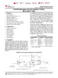
Transcription of 12 OUTPUT LED FLASHER MULTI-PATTERN
1 112 OUTPUT LED FLASHER multi -PATTERNPSELEDF12 ELECTRICAL SPECIFICATIONI nput Voltage Range+10 Vdc to +16 VdcOutput Drive Current3 Amps per OutputOperating Temperature-40 C to +85 CFlash PatternsQuint, Quad, Triple, Double,180 fpm Alternating Single,120 fpm Alternating Single,120 fpm Simultaneous Single,90 fpm Alternating Single,90 fpm Simultaneous Single,75 fpm Alternating Single,75 fpm Simultaneous Single,Cycle FlashSweep (Lightbar version only)Fast RandomOutput Drive MethodLow-side switchedPattern Control Method1 Serial Programminginput, 3 Progressive Operationmode inputs, Front & RearCutoff inputsStandby Current<10mA @ VdcReverse Polarity ProtectionYesShort Circuit ProtectionYesThermal ProtectionYesMECHANICAL SPECIFICATIONSW eather resistancePotted to protect circuitry, but " x " x.
2 75"WARNINGThis device is intended for use with LED Lights ONLY!! Use of this product on an Incandescent, Halogen orany light source other than LED's may damage the unit and void the use of this or any warning device does not insure that all drivers can or will observe or react to anemergency warning signal. Never take the right-of-way for granted. It is your responsibility to be sure youcan proceed safely before entering an intersection, driving against traffic, responding at a high rate ofspeed, or walking on or around traffic effectiveness of this warning device is highly dependent upon correct mounting and wiring.
3 Read andfollow the manufacturer's instructions before installing or using this device. The vehicle operator shouldinsure daily that all features of the device operate correctly. In use, the vehicle operator should insure theprojection of the warning signal is not blocked by vehicle components( , open trunks or compartmentdoors), people, vehicles, or other obstructions. This equipment is intended for use by authorized personnelonly. It is the user's responsibility to understand and obey all laws reguarding emergency warning user should check all applicable city, state and federal laws and 3, Inc.
4 , assumes no liability for any loss resulting from the use of this warning device. Properinstallation is vital to the performance of this warning device and the safe operation of the emergencyvehicle. It is important to recognize that the operator of the emergency vehicle is under psychological andphysiological stress caused by the emergenct situation. The warning device should be installed in such amanner as to A) Not reduce the OUTPUT performance of the system, B) Place the controls within convenientreach of the operator so that he can operate the system without losing eye contact with the warning devices often require high electrical voltages and/or currents.
5 Properly protect and usecaution around live electrical connections. Grounding or shorting of electrical connections can cause highcurrent arcing, which can cause personal injury and/or severe vehicle damage, including INSTALLATION COMBINED WITH OPERATOR TRAINING IN THE PROPER USE OF EMERGENCYWARNING DEVICES IS ESSENTIAL TO INSURE THE SAFETY OF EMERGENCY PERSONNEL AND THE WARNINGThis FLASHER is NOT waterproof!! This unit mustbe installed in a location protected from device is designed to flash Code 3, Inc. 12 voltLED-EX Lights up to 3 amps load per OUTPUT . DO NOTconnect more than a 3 amp load(two single LED-EXequivalent) to the OUTPUT .
6 Doing so will shut the unitdown to prevent damage to the Designation:J4,J5: PS FrontJ6: PS Rear CornerJ2,J3: DS FrontJ1: DS Rear CornerJ7,J12 : PS RearJ8: PS Front CornerJ9,J10 : DS RearJ11: DS Front CornerLightbar Configurations:When using this product as a lightbar FLASHER , the FLASHER outputs should be connected as follows (referto ):Figure2 Lightbar Installation:(Refer to Figure 3 and 4)1.) Plug the Control Harness into the ) Connect the +12V and ground wires to quickslide terminals E1 & E2 respectively. Use 14Ga. wire for the main +12V and ground : GND, terminal E2 can be grounded to the lightbar frame.
7 Ensure that the power wire isfused with a 15 Amp AUTO style ) Connect the white(Mode1), red/blk(Mode2), and red(Mode3) wires to three 18Ga. wires on the lightbar cable harness. Ensure that wire colors are marked on the lightbar wire-tag ) Connect the yellow(Flash Pattern PGM) wire to an 18 Ga. wire on the lightbar cable harness. Ensure that the chosen wire color is marked on the lightbar wire-tag sheet. The PGM wire can then be connected to a momentary +12V switch and used to program the desired flash pattern for any of the lightbar's three operating ) Connect the green(Front Cutoff) and blue(Rear Cutoff) wires to two 18Ga.
8 Wires on the lightbar cable harness. Ensure that the chosen wire colors are marked on the lightbar wire-tag Versions:This product is available in two different versions:1. Lightbar FLASHER version p/n T08111:This version can be requested using model no. (XXXXXX). This version has AMP Mate & Lock and DUAC/PLconnectors attached to the end of 5" and 3" wire harnesses respectively. This version is designed to fitcomfortably inside the Code3 LEDX 2100 lightbar, as well as Excalibur, CODE 360 and Javelin Remote LED FLASHER version p/n T08097:This version has the same connector interface as the Low Profile version, except that this version utilizesdirect circuit board headers rather than wire harnesses.
9 This FLASHER can be used as a remote LED FLASHER todrive Code 3 LED-EX and LED Perimeter lights. It can also be used as a motorcycle LED AWG RED/BLACKCONTROL HARNESS WIRE DESIGNATION:18 AWG BROWN18 AWG RED18 AWG WHITE18 AWG YELLOW18 AWG GREEN18 AWG BLUE1234567891011122. Blue:10-16V Rear Cutoff3. Yellow:10-16V Flash Pattern PGM4. White:10-16V Mode15. Brown:Not Used8. Green:10-16V Front :10-16V :10-16V :Not UsedINSTALLATION & WIRING1. First, install the FLASHER in a protected location using the FLASHER itself as a template. Make sure all connectorsare easily accessible. (Refer to Figure 5 and 6 for the following steps).
10 2. Plug in the Control Harness provided with the FLASHER p/n Connect the +12V and ground wires to quickslide terminals E1 & E2 respctively. Ensure that the +12V powerwire is fused with a 15 Amp Auto style fuse. Note: Use 14 Ga. wire for the main +12V and Optional: Connect the yellow wire (flash pattern) program wire to +12V through a momentary switch. Thisswitch can be used to program a different flash pattern for regular and Interclear operation. This wire can alsobe taped away or permanently grounded after the FLASHER has been programmed with the desired Optional: Connect the white (Interclear Enable) wire to the active high interclear OUTPUT on the siren Connect the green (Group B & C Enable) wire and the blue (Group A Enable) wire to +12V through two usesupplied SPST switches.