Transcription of 2.7 V to 5.5 V, Serial-Input, Voltage-Output, 16-Bit DACs ...
1 V to V, Serial-Input, Voltage-Output, 16-Bit DACs data sheet AD5541/AD5542 Rev. F Information furnished by Analog Devices is believed to be accurate and reliable. However, no responsibility is assumed by Analog Devices for its use, nor for any infringements of patents or other rights of third parties that may result from its use. Specifications subject to change without notice. No license is granted by implication or otherwise under any patent or patent rights of Analog Devices. Trademarks and registered trademarks are the property of their respective owners. One Technology Way, Box 9106, Norwood, MA 02062-9106, Tel: Fax: 1999 2012 Analog Devices, Inc. All rights reserved. FEATURES Full 16-Bit performance 3 V and 5 V single-supply operation Low mW power dissipation 1 s settling time Unbuffered voltage output capable of driving 60 k loads directly SPI-/QSPI-/MICROWIRE-compatible interface standards Power-on reset clears DAC output to 0 V (unipolar mode) 5 kV HBM ESD classification Low glitch: nV-sec APPLICATIONS Digital gain and offset adjustment Automatic test equipment data acquisition systems Industrial process control GENERAL DESCRIPTION The AD5541/AD5542 are single, 16-Bit , serial input, voltage output digital-to -analog converters (DACs) that operate from a single V to V supply.
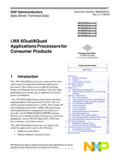
2 The DAC output range extends from 0 V to VREF. The DAC output range extends from 0 V to VREF and is guaranteed monotonic, providing 1 LSB INL accuracy at 16 bits without adjustment over the full specified temperature range of 40 C to +85 C. Offering unbuffered outputs, the AD5541/AD5542 achieve a 1 s settling time with low power consumption and low offset errors. Providing a low noise performance of nV/ Hz and low glitch, the AD5541/AD5542 is suitable for deployment across multiple end systems. The AD5542 can be operated in bipolar mode, which generates a VREF output swing. The AD5542 also includes Kelvin sense connections for the reference and analog ground pins to reduce layout sensitivity. The AD5541/AD5542 utilize a versatile 3-wire interface that is compatible with SPI, QSPI , MICROWIRE and DSP interface standards. The AD5541/AD5542 are available in 8-lead and 14-lead SOIC packages. FUNCTIONAL BLOCK DIAGRAMS 6128716-BIT DAC16-BIT DAC LATCHSERIAL INPUT REGISITERVDDDGNDDINREFCSSCLK345 VOUTAGNDAD5541 CONTROLLOGIC07557-001 Figure 1.
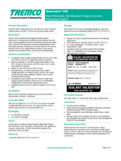
3 AD5541 1123141216-BIT DAC16-BIT DAC LATCHSERIAL INPUT REGISITERVDDDGNDLDACREFFCSDIN6 REFS5710 VOUT13 INV1 RFBAGNDF4 AGNDSAD5542 CONTROLLOGIC07557-0028 SCLKRFBRINV Figure 2. AD5542 Table 1. Part No. Description AD5541A/AD5542A Single, 16-Bit unbuffered nanoDAC , 1 LSB INL, LFCSP AD5024/AD5044/AD5064 Quad 12-/14-/ 16-Bit nanoDAC, 1 LSB INL, TSSOP AD5062 Single, 16-Bit nanoDAC, 1 LSB INL, SOT-23 AD5063 Single, 16-Bit nanoDAC, 1 LSB INL, SOT-23 PRODUCT HIGHLIGHTS 1. Single-Supply Operation. The AD5541 and AD5542 are fully specified and guaranteed for a single V to V supply. 2. Low Power Consumption. These parts consume typically mW with a 5 V supply and mV at 3 V. 3. 3-Wire Serial Interface. 4. Unbuffered Output Capable of Driving 60 k Loads. This reduces power consumption because there is no internal buffer to drive. 5. Power-On Reset Circuitry. AD5541/AD5542 data sheet Rev. F | Page 2 of 20 TABLE OF CONTENTS Features .. 1 Applications.
4 1 General Description .. 1 Functional Block Diagrams .. 1 Product Highlights .. 1 Revision History .. 2 Specifications .. 3 Timing Characteristics .. 4 Absolute Maximum Ratings .. 5 ESD Caution .. 5 Pin Configurations and Function Descriptions .. 6 Ty pi ca l Performance Characteristics .. 7 Terminology .. 10 Theory of Operation .. 11 Digital-to-Analog Section .. 11 Serial Interface .. 11 Unipolar Output Operation .. 11 Bipolar Output Operation .. 12 Output Amplifier Selection .. 12 Force Sense Amplifier Selection .. 12 Reference and Ground .. 12 Power-On Reset .. 13 Power Supply and Reference Bypassing .. 13 Microprocessor Interfacing .. 14 AD5541/AD5542 to ADSP-21xx Interface .. 14 AD5541/AD5542 to 68HC11/68L11 14 AD5541/AD5542 to MICROWIRE Interface .. 14 AD5541/AD5542 to 80C51/80L51 Interface .. 14 Applications Information .. 15 Optocoupler Interface .. 15 Decoding Multiple AD5541/AD5542s .. 15 Outline Dimensions .. 16 Ordering Guide.
5 17 REVISION HISTORY 3/12 Rev. E to Rev. F Change to Figure 19 .. 9 Changes to Ordering Guide .. 17 3/11 Rev. D to Rev. E Changed +105 C to +85 C, General Description Section .. 1 2/11 Rev. C to Rev. D Changes to Features Section, General Description Section, Product Highlights Section .. 1 Added Table 1; Renumbered Sequentially .. 1 Added Output Noise Spectral Density Parameter and Output Noise Parameter, Table 3 Changes to Ordering Guide .. 17 4/10 Rev. B to Rev. C Changes to General Description Section .. 1 Changes to Features List .. 1 Changes to Product Highlights .. 1 Changes to Table 1 .. 3 Changes to Table 3 .. 5 Changes to Figure 16, Figure 17, and Figure 19 .. 8, 9 Changes to Theory of Operations Section .. 11 Changes to Microprocessor Interfacing Section .. 14 Changes to Outline Dimensions .. 16 Changes to Ordering Guide .. 17 8/08 Rev. A to Rev. B Updated Format .. Universal Changes to Timing Characteristics Section .. 4 Changes to Table 3.
6 5 Updated Outline Dimensions .. 16 Changes to Ordering Guide .. 17 10/99 Rev. 0 to Rev. A data sheet AD5541/AD5542 Rev. F | Page 3 of 20 SPECIFICATIONS VDD = V to V, V VREF VDD, AGND = DGND = 0 V. All specifications TA = TMIN to TMAX, unless otherwise noted. Table 2. Parameter1 Min Typ Max Unit Test Conditions STATIC PERFORMANCE Resolution 16 Bits Relative Accuracy (INL) LSB L, C grades LSB B, J grades LSB A grade Differential Nonlinearity (DNL) LSB Guaranteed monotonic LSB J grade Gain Error + 2 LSB TA = 25 C 3 LSB Gain Error Temperature Coefficient ppm/ C Unipolar Zero Code Error LSB TA = 25 C LSB Unipolar Zero Code Temperature Coefficient ppm/ C AD5542 Bipolar Resistor Matching / RFB/RINV, typically RFB = RINV = 28 k % Ratio error Bipolar Zero Offset Error 1 5 LSB TA = 25 C 6 LSB Bipolar Zero Temperature Coefficient ppm/ C Bipolar Zero Code Offset Error 1 5 LSB TA = 25 C 6 LSB Bipolar Gain Error +1 5 LSB TA = 25 C 6 LSB Bipolar Gain Temperature Coefficient ppm/ C OUTPUT CHARACTERISTICS Output Voltage Range 0 VREF 1 LSB V Unipolar operation VREF VREF 1 LSB V AD5542 bipolar operation Output Voltage Settling Time 1 s To 1/2 LSB of FS, CL = 10 pF Slew Rate 17 V/ s CL = 10 pF.
7 Measured from 0% to 63% Digital-to-Analog Glitch Impulse nV-sec 1 LSB change around the major carry Digital Feedthrough nV-sec All 1s loaded to DAC, VREF = V DAC Output Impedance k Tolerance typically 20% Output Noise Spectral Density nV/ Hz DAC code = 0x8400, frequency = 1 kHz Output Noise V p-p Hz to 10 Hz Power Supply Rejection Ratio LSB VDD 10% DAC REFERENCE INPUT Reference Input Range VDD V Reference Input Resistance2 9 k Unipolar operation k AD5542, bipolar operation LOGIC INPUTS Input Current 1 A Input Low Voltage, VINL V Input high Voltage, VINH V Input Capacitance3 10 pF Hysteresis Voltage3 V REFERENCE 3 Reference 3 dB Bandwidth MHz All 1s loaded Reference Feedthrough 1 mV p-p All 0s loaded, VREF = 1 V p-p at 100 kHz Signal-to-Noise Ratio 92 dB Reference Input Capacitance 26 pF Code 0x0000 26 pF Code 0xFFFF AD5541/AD5542 data sheet Rev.
8 F | Page 4 of 20 Parameter1 Min Typ Max Unit Test Conditions POWER REQUIREMENTS Digital inputs at rails VDD V IDD 125 150 A Power Dissipation mW 1 Temperature ranges are as follows: A, B, C versions: 40 C to +85 C; J, L versions: 0 C to 70 C. 2 Reference input resistance is code-dependent, minimum at 0x8555. 3 Guaranteed by design, not subject to production test. TIMING CHARACTERISTICS VDD = V to V 10%, VREF = V, VINH = 3 V and 90% of VDD, VINL = 0 V and 10% of VDD, AGND = DGND = 0 V; 40 C < TA < +85 C, unless otherwise noted. Table 3. Parameter1, 2 Limit Unit Description fSCLK 25 MHz max SCLK cycle frequency t1 40 ns min SCLK cycle time t2 20 ns min SCLK high time t3 20 ns min SCLK low time t4 10 ns min CS low to SCLK high setup t5 15 ns min CS high to SCLK high setup t6 30 ns min SCLK high to CS low hold time t7 20 ns min SCLK high to CS high hold time t8 15 ns min data setup time t9 4 ns min data hold time (VINH = 90% of VDD, VINL = 10% of VDD) t9 ns min data hold time (VINH = 3V, VINL = 0 V) t10 30 ns min LDAC pulse width t11 30 ns min CS high to LDAC low setup t12 30 ns min CS high time between active periods 1 Guaranteed by design and characterization.
9 Not production tested 2 All input signals are specified with tR = tF = 1 ns/V and timed from a voltage level of (VINL + VINH)/2. SCLKCSDINDB15 LDAC*t6t4t12t8t5t2t3t1t7t5t11t10*AD5542 ONLY. CAN BE TIED PERMANENTLY LOW IF Figure 3. Timing Diagram data sheet AD5541/AD5542 Rev. F | Page 5 of 20 ABSOLUTE MAXIMUM RATINGS TA = 25 C, unless otherwise noted. Table 4. Parameter Rating VDD to AGND V to +6 V Digital Input Voltage to DGND V to VDD + V VOUT to AGND V to VDD + V AGND, AGNDF, AGNDS to DGND V to + V Input Current to Any Pin Except Supplies 10 mA Operating Temperature Range Industrial (A, B, C Versions) 40 C to +85 C Commercial (J, L Versions) 0 C to 70 C Storage Temperature Range 65 C to +150 C Maximum Junction Temperature (TJ max) 150 C Package Power Dissipation (TJ max TA)/ JA Thermal Impedance, JA SOIC (R-8) C/W SOIC (R-14) C/W Lead Temperature, Soldering Peak Temperature1 260 C ESD2 5 kV Stresses above those listed under Absolute Maximum Ratings may cause permanent damage to the device.
10 This is a stress rating only; functional operation of the device at these or any other conditions above those indicated in the operational section of this specification is not implied. Exposure to absolute maximum rating conditions for extended periods may affect device reliability. ESD CAUTION 1 As per JEDEC Standard 20. 2 HBM Classification. AD5541/AD5542 data sheet Rev. F | Page 6 of 20 PIN CONFIGURATIONS AND FUNCTION DESCRIPTIONS VOUT1 AGND2 REF3CS4 VDD8 DGND7 DIN6 SCLK5AD5541 TOP VIEW(Not to Scale)07557-004 Figure 4. AD5541 Pin Configuration Table 5. AD5541 Pin Function Descriptions Pin No. Mnemonic Description 1 VOUT Analog Output Voltage from the DAC. 2 AGND Ground Reference Point for Analog Circuitry. 3 REF Voltage Reference Input for the DAC. Connect to an external V reference. Reference can range from 2 V to VDD. 4 CS Logic Input Signal. The chip select signal is used to frame the serial data input. 5 SCLK Clock Input.