Transcription of 30 V, Low Noise, Rail-to-Rail Input/Output, Low Power ...
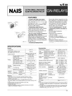
1 30 V, Low Noise, Rail-to-Rail Input/ output , Low Power operational Amplifiers data sheet ada4084 -1/ ada4084 -2/ ada4084 -4 Rev. I Document Feedback Information furnished by analog devices is believed to be accurate and reliable. However, no responsibility is assumed by analog devices for its use, nor for any infringements of patents or other rights of third parties that may result from its use. Specifications subject to change without notice. No license is granted by implication or otherwise under any patent or patent rights of analog devices . Trademarks and registered trademarks are the property of their respective owners. One Technology Way, Box 9106, Norwood, MA 02062-9106, Tel: 2011 2017 analog devices , Inc. All rights reserved. Technical Support FEATURES Rail-to-r ail input/ output Low Power : mA typical per amplifier at 15 V Gain bandwidth product: MHz at AV = 100 typical Unity-gain crossover: MHz typical 3 dB closed-l oop bandwidth: MHz typical at 15 V Low offset voltage: 100 V maximum (SOIC) Unity-gain stable High slew rate: V/ s typical Low noise: nV/ Hz typical at 1 kHz Long-term offset voltage drift (10,000 hours): 3 V typical Temperature hysteresis: 4 V typical APPLICATIONS Battery-powered instrumentation High-side and low-side sensing Power supply control and protection Telecommunications Digital-to- analog converter (DAC) output amplifiers analog -to-digital converter (ADC) input buffers PIN CONNECTION DIAGRAM 08237-001 NOTES1.
2 FOR THE LFCSP PACKAGE,THE EXPOSED PAD MUST BECONNECTED TO V .3+IN A4V 1 OUT A2 IN A6 IN B5 +IN B8 V+7 OUT BADA4084-2 Figure 1. ada4084 -2, 8-Lead LFCSP (CP); for Additional Packages and Models, See the Pin Configurations and Function Descriptions Section GENERAL DESCRIPTION The ada4084 -1 (single), ada4084 -2 ( dual), and ada4084 -4 (quad) are s ingle-supply, 10 MHz bandwidth amplifiers featuring rail-to -rail inputs and outputs. They are guaranteed to operate from +3 V to +30 V (or V to 15 V). These amplifiers are well suited for single-supply applications requiring both ac and precision dc performance. The combination of wide bandwidth, low noise, and precision makes the ada4084 -1/ ada4084 -2/ ada4084 -4 useful in a wide variety of applications, including filters and instrumentation. Other applications for these amplifiers include portable telecom-munications equipment, Power supply control and protection, and use as amplifiers or buffers for transducers with wide output ranges.
3 Sensors requiring a rail-to -rail input amplifier include Hall effect, piezoelectric, and resistive transducers. The ability to swing rail to rail at both the input and output enables designers to build multistage filters in single-supply systems and to maintain high signal-to -noise ratios. The ada4084 -1/ ada4084 -2/ ada4084 -4 are s pecified over the industrial temperature range of 40 C to +125 C. The single ada4084 -1 is available in the 5- lead SOT-23 and 8- lead SOIC; the dual ada4084 -2 is available in the 8- lead SOIC, 8-lead MSOP, and 8-lead LFCSP surface-mount packages; and the ada4084 -4 is offered in the 14-lead TSSOP and 16-lead LFCSP. The ada4084 -1/ ada4084 -2/ ada4084 -4 are members of a growing series of high voltage, low noise op amps offered by analog devices , Inc. (see Ta b l e 1). Table 1. Low Noise Op Amps Single Dual Quad Voltage Noise AD8597 AD8599 nV/Hz ADA4004-1 ADA4004-2 ADA4004-4 nV/Hz AD8675 AD8676 nV/Hz Rail-to-Rail output AD8671 AD8672 AD8674 nV/Hz OP27, OP37 nV/Hz ada4084 -1 ada4084 -2 ada4084 -4 nV/Hz Rail-to-Rail input/ output ada4084 -1/ ada4084 -2/ ada4084 -4 data sheet Rev.
4 I | Page 2 of 36 TABLE OF CONTENTS Features .. 1 Applications .. 1 Pin Connection Diagram .. 1 General Description .. 1 Revision History .. 2 Specifications .. 4 Electrical Characteristics .. 4 Absolute Maximum Ratings .. 7 Thermal Resistance .. 7 ESD Caution .. 7 Pin Configurations and Function Descriptions .. 8 Typical Performance Characteristics .. 11 V Characteristics .. 11 5 V Characteristics .. 17 15 V Characteristics .. 23 Applications Information .. 29 Functional Description .. 29 Start-Up Characteristics .. 30 Input Protection .. 30 output Phase Reversal .. 30 Designing Low Noise Circuits in Single-Supply Applications .. 31 Comparator Operation .. 31 Long-Term Drift .. 32 Temperature Hysteresis .. 32 Outline Dimensions .. 33 Ordering Guide .. 36 REVISION HISTORY 5/2017 Rev. H to Rev. I Changed CP-8-12 to CP-8-11 .. Throughout Changed CP-16-26 to CP-16-17 .. Throughout Changes to Features 1 Added Long-Term Drift Section, Temperature Hysteresis Section, Figure 112, Figure 113, and Figure 114; Renumbered Sequentially.
5 32 Updated Outline Dimensions .. 34 Changes to Ordering Guide .. 36 8/2015 R e v. G to R e v. H Added 5-Lead SOT-23 .. Universal Changes to Pin Connection Diagram Section, Figure 1, and General Description Section .. 1 Deleted Figure 3; Renumbered Sequentially .. 1 Changes to Large Signal Voltage Gain Parameter, Table 2 .. 4 Changes to Large Signal Voltage Gain Parameter, Table 3 .. 5 Changes to Large Signal Voltage Gain Parameter, Table 4 .. 6 Changes to Table 6 .. 7 Moved Figure 3 .. 8 Added Pin Configurations and Function Descriptions Section, Figure 4, Figure 5, Ta b l e 7 , Ta b l e 8, and Table 9; Renumbered Sequentially .. 8 Added Figure 6, Figure 7 , Figure 8, Table 10, and Table 11 .. 9 Moved Figure 9 .. 10 Added Table 12 .. 10 Added Figure 11 and Figure 11 Added Figure 42 and Figure 17 Added Figure 73 and Figure 23 Updated Outline Dimensions .. 32 Changes to Ordering Guide.
6 35 6/2015 Rev. F to Rev. G Changes to Figure 96 and Figure 24 1/2015 Rev. E to Rev. F Moved Revision History .. 3 Changes to Table 5 .. 7 Changes to Ordering Guide .. 29 7/2014 R e v. D t o R e v. E Added ada4084 -1 .. Universal Added Figure 1; Renumbered Sequentially .. 1 Changes to output Voltage High Parameter, Table 2 .. 3 Changes to Current Noise Density Parameter, Table 3 .. 4 Changes to Current Noise Density Parameter, Table 4 .. 5 Changes to Figure 8 Caption, and Figure 9 to Figure 11 .. 7 Changes to Figure 13 .. 8 Changes to Figure 21 .. 9 Added Figure 31; Renumbered Sequentially .. 11 Changes to Figure 30 Caption, and Figure 32 to Figure 34 .. 11 Changes to Figure 36 Caption to Figure 39 Caption .. 12 Changes to Figure 50 .. 14 Added Figure 60 .. 16 Changes to Figure 59 Caption, Figure 62, and Figure 63 .. 16 Changes to Figure 65 Caption to Figure 68 Caption .. 17 Changes to Figure 79.
7 19 Added Figure 89 .. 21 Changes to Figure 88 Caption, Figure 91 Caption, and Figure 92 Caption .. 21 Changes to Ordering Guide .. 28 data sheet ada4084 -1/ ada4084 -2/ ada4084 -4 Rev. I | Page 3 of 36 11/2013 R e v. C to R e v. D Added 14-Lead TSSOP and 16-Lead LFCSP Packages .. Universal Added ada4084 -4 .. Universal Change to Features Section and Applications Section .. 1 Added Figure 2 and Figure 3; Renumbered Sequentially .. 1 Changes to Table 2 .. 3 Changes to Table 3 .. 4 Changes to Table 4 .. 5 Changes to Table 5 and Table 6 .. 6 Changes to Typical Performance Characteristics Section .. 7 Updated Outline Dimensions .. 27 Changes to Ordering Guide .. 28 4/2013 Rev. B to Rev. C Changes to Figure 48 Caption .. 15 Updated Outline Dimensions .. 25 6/2012 Rev. A to Rev. B Added LFCSP Universal Changes to Figure 1 .. 1 Changes to output Voltage High Parameter, Table 4 .. 5 Added Figure 5 and Figure 7, Renumbered Sequentially.
8 7 Added Figure 30 and Figure 32 .. 12 Added Figure 55 and Figure 57 .. 17 Added Startup Characteristics Section .. 23 Moved Figure 78 .. 23 Changes to output Phase Reversal Section and Comparator Operation Section .. 24 Updated Outline Dimensions .. 25 Changes to Ordering Guide .. 26 2/2012 R e v. 0 to Rev. A Changes to data sheet Title .. 1 Changes to Voltage Range in General Description .. 1 Changes to Supply Current/ amplifier Parameter, Table 2 .. 3 Changes to Common-Mode Rejection Ratio Parameter, Table 3 .. 4 Changes to Common-Mode Rejection Ratio Parameter, Table 4 .. 5 Changes to Figure 2 .. 6 Changes to Figure 24 .. 10 Changes to Figure 32 .. 12 Changes to Figure 47 .. 14 Changes to Figure 55 .. 16 Changes to Figure 62 .. 17 Changes to Figure 73 .. 20 10/2011 Revision 0: Initial Ve r s i o n ada4084 -1/ ada4084 -2/ ada4084 -4 data sheet Rev. I | Page 4 of 36 SPECIFICATIONS ELECTRICAL CHARACTERISTICS VSY = 3 V, VCM = V, TA = 25 C, unless otherwise noted.
9 Table 2. Parameter Symbol Test Conditions/Comments Min Typ Max Unit INPUT CHARACTERISTICS Offset Voltage VOS SOIC package 20 100 V 40 C TA +125 C 200 V SOT-23, MSOP, TSSOP packages 50 130 V 40 C TA +125 C 250 V ada4084 -2 LFCSP package 80 200 V 40 C TA +125 C 300 V Offset Voltage Drift t/ T 40 C TA +125 C V/ C Offset Voltage Matching TA = 25 C 150 V ada4084 -4 LFCSP package 200 V Input Bias Current IB 140 250 nA 40 C TA +125 C 400 nA Input Offset Current IOS 5 25 nA 40 C TA +125 C 50 nA Input Voltage Range 0 3 V Common-Mode Rejection Ratio CMRR VCM = 0 V to 3 V 64 88 dB 40 C TA +125 C 60 dB Large Signal Voltage Gain AVO RL = 2 k , V VOUT V 100 104 dB 40 C TA +125 C 97 dB Input Impedance Differential 100|| k ||pF Common Mode 80|| M ||pF output CHARACTERISTICS output Voltage High VOH RL = 10 k to VCM V 40 C TA +125 C V RL = 2 k to VCM V 40 C TA +125 C V output Voltage Low VOL RL = 10 k to VCM 10 20 mV 40 C TA +125 C 40 mV RL = 2 k to VCM 20 30 mV 40 C TA +125 C 50 mV Short-Circuit Current ISC 17/+10 mA Closed-Loop output Impedance ZOUT f = 1 kHz, AV = 1 Power SUPPLY Power Supply Rejection Ratio PSRR VSY = V to V 100 110 dB 40 C TA +125 C 90 dB Supply Current per amplifier ISY IOUT = 0 mA mA 40 C TA +125 C mA DYNAMIC PERFORMANCE Slew Rate SR RL = 2 k V/ s Gain Bandwidth Product GBP VIN = 5 mV p-p, RL = 10 k.
10 AV = 100 MHz Unity-Gain Crossover UGC VIN = 5 mV p-p, RL = 10 k , AV = 1 MHz Phase Margin M 86 Degrees 3 dB Closed-Loop Bandwidth 3 dB AV = 1, VIN = 5 mV p-p MHz Settling Time tS AV = 10, VIN = 2 V p-p, 4 s Total Harmonic Distortion Plus Noise THD + N VIN = 300 mV rms, RL = 2 k , f = 1 kHz % NOISE PERFORMANCE Voltage Noise en p-p Hz to 10 Hz V p-p Voltage Noise Density en f = 1 kHz nV/ Hz Current Noise Density in f = 1 kHz pA/ Hz data sheet ada4084 -1/ ada4084 -2/ ada4084 -4 Rev. I | Page 5 of 36 VSY = V, VCM = 0 V, TA = 25 C, unless otherwise noted. Table 3. Parameter Symbol Test Conditions/Comments Min Typ Max Unit INPUT CHARACTERISTICS Offset Voltage VOS SOIC package 30 100 V 40 C TA +125 C 200 V SOT- 23, MSOP, TSSOP packages 60 130 V 40 C TA +125 C 250 V ada4084 -2 LFCSP package 90 200 V 40 C TA +125 C 300 V Offset Voltage Drift VOS/ T 40 C TA +125 C V/ C Offset Voltage Matching TA = 25 C 150 V ada4084 -4 LFCSP package 200 V Input Bias Current IB 140 250 nA 40 C TA +125 C 400 nA Input Offset Current IOS 5 25 nA 40 C TA +125 C 50 nA Input Voltage Range 5 +5 V Common-Mode Rejection Ratio CMRR VCM = 4 V , 40 C TA +125 C 106 124 dB VCM = 5 V 76 dB VCM = 5 V, 40 C TA +125 C 70 dB Large Signal Voltage Gain AVO RL = 2 k.