Transcription of A Power Meter based on the AD-8307 from Analog Devices.
1 A Power Meter based on the AD- 8307 from section relates to the QST paper that Bob Larkin (W7 PUA) and Ipublished in QST for June, 2001 Update, 10 Mar07, 5 June07 Calibration at the Frequency March 07, 5 June07I discovered a problem with the version of the Meter at had beentrying to build a wide frequency range return loss bridge and had seen problemsat the high end, between 400 and 500 MHz, the upper limit of had been using the homebrew Power Meter to measure theOpen to Short ratio over the to 500 MHz spectrum.
2 (See the bridgediscussion in EMRFD.)I finally borrowed a HP435 Power Meter with a 4 GHzelement from a local friend to check the output accuracy of my HP8640 Bsignal generator and to then study the accuracy of my homebrew Power first conclusion reached is that the HP8640B signal generator is extremelyaccurate with regard to output Power versus that indicated by the front accuracy seemed to only be limited by the resolution of the has been my experience with other HP signal checkedcalibration at 10 and 500 MHz.
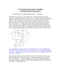
3 And a few frequencies other conclusion is less calibrated the AD8307 basedpower Meter at several frequencies and found that the calibration wascompromised at the high results I got at 10 MHz and at 500 MHzare plotted that the points at the high end are not on the linearcurve fit line at higher powers at 500 points are not evenly spacedlike they are at 10 MHz. The plots consist of a solid blue line, which is theequation listed, and round data markers showing the Power from the generatoron the Y axis and the DVM readingon the X equation wasdetermined from a curve fitting routine in does not mean that the Power Meter should not be used over the fullfrequency , if you are after the best results, you should doyour own was seeing an error of about 2 dB in my 500 MHzresults, which was enough to severely confuse the experiments (as well as theexperimenter.)
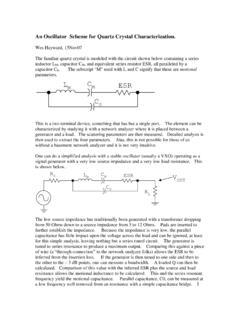
4 Please don't use the calibration results listed above foryour ownpower , 5 June 07:After the alarming results reported above, I decided that it was time to get somemusclebehind the observations and I ask Bob Larkin, W7 PUA, to take a lookat the started by using the sweeper part of his HP8714B networkanalyzer to drive his HP Power Meter , an HP435A with an HP8481A two agreed within dB over the range of the Power sweeperwas found to be flat within .05 dB at powers between-20 and +10 then examined his version of the AD8307 based Power has an A to D input with the ability to output digital data to was used to record the output of the 8307 Power Meter for later results are shown below.
5 These results from W7 PUA are extremely data is reasonableat powers of-10 dBm and , the calibration becomescompromised at the high frequency end as the Power is extremely wide range of the homebrew Power Meter means that we stillhave a lot of room for that is required is to keep the powerbelow-10 is some curvature to the sweeps shown above, even atlow Power , but this was of no consequence in the bridge measurements I wasdoing (mentioned above) where I was comparing results at each are several lessons that become apparent from this are only as good as the calibration we use with our we really need accurate results, we had better figure out a way to calibrateour homebrew measurement assumption that a compensation doneat one Power level will extend to others is not valid.
6 (The compensation inquestion here is the input RLC network preceding the AD8307 detector chip.)This is especially true withsomething as grossly nonlinear as a could have detected some of the problems with carefulapplication of a step refined and updated data is not acondemnation of the , it is just an observation that the part islimited in its is still a spectacular integrated is areminder of why we build spectrum and network analyzers that use mixers todo the more refined thanks to Bob for the enlighteningmeasurements!
7 The Analog devices AD- 8307 is now available from DigiKey , look at the Analog devices web site, for you my qualify to get a devices has become the leader in the industry in recent times in theway they provide engineering samples and we thank them for this policy!2 June 2004,10 March is a Power Meter ?Seems like an odd question considering that we are answering it two years afterthe paper appeared in , it struck me that it was a questionworthy of Power Meter in the sense that we talked about it in our paper is an instrumentwith a built in Power is applied to the input jack and thepower delivered to the termination, usually 50 Ohms, is indicated on the Power Meter used either an internal Analog Meter movement or anexternal digital many manufacturers have built and soldpower meters .
8 Those most familiar to the amateur radio community are fromHewlett call this instrument a "lab Power Meter ."A popular instrument in the RF world is the "in-line Power Meter ."Thisequipment, typified by boxes manufactured by Bird, usually includes a built indirectional combination is capable then of measuring the flow ofpower in a transmission reversing the instrument, Power flow in areverse direction can be measured, allowing impedance matchto be ,in -line Power meters are capable of operation at the high Power levelsassociated with in-line Power Meter does not include lab Power Meter can certainly be used with an outboard directional couplerfor transmission line can also be used, with couplers or taps,to measure transmitter level powers during the lab instrumentsare more often used during the development of was thedominant application for our you are interested in an in-linepower Meter .
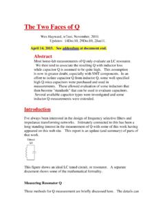
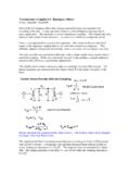
9 We recommend the design by Roy Lewallen presented in QST forFeb, paper is included on the EMRFD Dec 2003, :18 July01 whThe Power Meter paper from the June 2001 issue of QST (coauthored with BobLarkin, W7 PUA) had a couple of was an error in the main schematic, Fig. IN and the OUTlabels on U2, the 78L05 regulator should be Fig. 6:The 10 dB pad is used between the tap attenuated output and thepower does not go between the Power Meter and the DVM as Tap with BNC readers have built the Power Meter tap with BNC is theway I built there is often a problem, for some BNC connectors willprotrude well into the box.
10 Leaving no room for the large brass transmission is a simple two nuts with each BNC then puts the BNC center connector nearly flush with the isshown in the following even better solution would use flangemount BNC connectors, available from DigiKey or Mouser, among your Power got a couple of notes from folks who had trouble with the equation we usedwith a DVM to read is a calibration that the builder must do forhis or her Power procedure is shown below:Application Hints for the Power Meter .(May 26, 2002)A.