Transcription of AD421 data sheet - Analog Devices
1 A Loop-Powered 4 mA to 20 mA DAC. AD421 . FEATURES FUNCTIONAL BLOCK DIAGRAM. 4 mA to 20 mA Current Output HART Compatible REF IN REF OUT1 REF OUT2. 16-Bit Resolution and Monotonicity (+ ) (+ ) (+ ) LV VCC. Integral Nonlinearity 5 V or 3 V Regulator Output . 75k . V and V Precision Reference AD421 . 750 A Quiescent Current max 134k . Programmable Alarm Current Capability BANDGAP DRIVE. Flexible High Speed Serial Interface REFERENCE. 121k COMP. 16-Lead SOIC and PDIP Packages LOCAL BOOST. OSCILLATOR. data INPUT SHIFT. CLOCK REGISTER. SWITCHED. 16-BIT CURRENT. LATCH DAC LATCH SIGMA- SOURCES. DELTA DAC AND 40 . GENERAL DESCRIPTION FILTERING. 80k LOOP. The AD421 is a complete, loop-powered, digital to 4 mA to POWER-ON. RTN. RESET. 20 mA converter, designed to meet the needs of smart trans- mitter manufacturers in the Industrial Control industry. It pro- COM C1 C2 C3.
2 Vides a high precision, fully integrated, low cost solution in a compact 16-lead package. The AD421 is ideal for extending the resolution of smart 4 mA to 20 mA transmitters at very low cost. PRODUCT HIGHLIGHTS. 1. The AD421 is a single chip, high performance, low cost The AD421 includes a selectable regulator that is used to power solution for generating 4 mA to 20 mA signals for smart itself and other Devices in the transmitter. This regulator pro- industrial control transmitters. vides either a +5 V, + V or +3 V regulated output voltage. The part also contains + V and + V precision references. 2. The AD421 's regulated supply voltage can be used to power The AD421 thus eliminates the need for a discrete regulator any additional circuits in the transmitter. The regulated and voltage reference. The only external components required output value is pin selectable as either +3 V, + V or +5 V.
3 Are a number of passive components and a pass transistor to 3. The AD421 's on-chip references can provide a precision span large loop voltages. reference voltage to other Devices in the system. This refer- The AD421 can be used with standard HART FSK protocol ence voltage can be either + V or + V. communication circuitry without any degradation in specified 4. The AD421 is fully compatible with standard HART cir- performance. The high speed serial interface is capable of oper- cuitry or other similar FSK protocols. ating at 10 Mbps and allows for simple connection to com- 5. With the addition of a single discrete transistor, the AD421 . monly-used microprocessors and microcontrollers via a standard can be operated from VCC + 2 V min to a maximum of the three-wire serial interface. breakdown voltage of the pass transistor. The sigma-delta architecture of the DAC guarantees 16-bit 6.
4 The AD421 converts the digital data to current with 16-bit monotonicity while the integral nonlinearity for the AD421 is resolution and monotonicity. Full-scale settling time to The part provides a zero scale 4 mA output current typically occurs within 8 ms. with offset error and a 20 mA full-scale output current with gain error. 7. The AD421 features a programmable alarm current capabil- ity that allows the transmitter to send out of range currents to The AD421 is available in a 16-lead, inch-wide, plastic DIP indicate a transducer fault. and in a 16-lead, inch-wide, SOIC package. The part is speci- fied over the industrial temperature range of 40 C to +85 C. HART is a registered trademark of the HART Communication Foundation. REV. C. Information furnished by Analog Devices is believed to be accurate and reliable. However, no responsibility is assumed by Analog Devices for its use, nor for any infringements of patents or other rights of third parties One Technology Way, Box 9106, Norwood, MA 02062-9106, which may result from its use.
5 No license is granted by implication or Tel: 781/329-4700 World Wide Web Site: otherwise under any patent or patent rights of Analog Devices . Fax: 781/326-8703 Analog Devices , Inc., 2000. (Using DN25D1 as pass transistor as per Figure 3;. AD421 LOOP-POWERED SPECIFICATIONS REF IN = REF OUT2; TA = TMIN to TMAX unless otherwise noted). Parameter B Versions2 Units Conditions/Comments OUTPUT CHARACTERISTICS. Current Loop Voltage Compliance3 VCC + 2 V min 350 V max DN25D Breakdown Voltage Full-Scale Settling Time 8 ms typ Settling Time to , C1 = C2 = 10 nF, C3 = nF. Output Impedance 25 M typ AC Loop Voltage Sensitivity 2 A/V typ 1200 Hz to 2200 Hz VOLTAGE REGULATOR. Output Voltage (VCC). 3 V Mode V min/V max 3 V Nominal. LV Pin Connected to VCC. V Mode V min/V max V Nominal. LV Pin Connected Through F to VCC. 5 V Mode V min/V max 5 V Nominal. LV Pin Connected to COM.
6 Externally Available Current mA min Assuming 4 mA Flowing in the Loop Line Regulation 1 V/V typ Load Regulation 15 V/mA typ DAC SPECIFICATIONS (V CC = +3 V to +5 V; REF IN = REF OUT2; TA = TMIN to TMAX unless otherwise noted). Parameter B Versions2 Units Conditions/Comments ACCURACY. Resolution 16 Bits Monotonicity 16 Bits min Integral Nonlinearity % of FS max FS = Full-Scale Output Current Offset (4 mA) @ +25 C4 % of FS max VCC = 5 V. Offset Drift 25 ppm of FS/ C max Includes On-Chip Reference Drift Total Output Error (20 mA) @ +25 C4 % of FS max VCC = 5 V. Total Output Drift 50 ppm of FS/ C max Includes On-Chip Reference Drift VCC Supply Sensitivity 50 nA/mV max 25 nA/mV Typical VOLTAGE REFERENCE. REF OUT2. Output Voltage V min/V max V Nominal Drift 40 ppm/ C max 20 ppm/ C Typical from 40 C to +25 C and ppm/ C Typical from +25 C to +85 C. Externally Available Current mA min VCC Supply Sensitivity 150 V/V max 15 V/V Typical Output Impedance 3 typ Noise ( Hz 10 Hz) 6 V (p-p) typ REF OUT1.
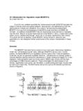
7 Output Voltage V min/V max V Nominal, 100 k Load to COM5. Drift 50 ppm/ C max 20 ppm/ C Typical from 40 C to +25 C and 2 ppm/ C Typical from +25 C to +85 C. Externally Available Current mA min VCC Supply Sensitivity 150 V/V max 15 V/V Typical Output Impedance 3 typ Noise ( Hz 10 Hz) 4 V (p-p) typ REF IN. Input Resistance 40 k typ DIGITAL INPUTS. VIH (Logic 1) VCC V min VIL (Logic 0) VCC V max IIH 10 A max VIN = VCC. IIL 10 A max VIN = 0 V. data Coding Binary data Rate 10 Mbps max POWER SUPPLIES. Operating Range + to + V min to V max Functional to 7 V. Quiescent Current @ VCC = 3 V 650 A max 475 A Typical @ VCC = 5 V 750 A max 575 A Typical NOTES. 1. The DN25D is available from Supertex, Inc., 1350 Bordeaux Drive, Sunnyvale, CA 94089. 2. Temperature range is 40 C to +85 C. 3. The max current loop voltage compliance is determined by the pass transistor breakdown voltage and is 350 V for the DN25D.
8 4. With VCC = 3 V, the transfer function shifts negative by typically ; a 16 k resistor connected between COM and LOOPRTN will approximately compensate for the V CC. supply sensitivity in moving from 5 V to 3 V by skewing the gain of the AD421 . 5. 100 k resistor only required if this reference is being used in application circuits. Specifications subject to change without notice. 2 REV. C. AD421 . TIMING CHARACTERISTICS1, 2, 3 (V CC = +3 V to +5 V, TA = TMIN to TMAX unless otherwise noted). Parameter (B Versions) Units Conditions/Comments tCK 100 ns min data Clock Period tCL 50 ns min data Clock Low Time tCH 50 ns min data Clock High Time tDW 30 ns min data Stable Width tDS 30 ns min data Setup Time tDH 0 ns min data Hold Time tLD 50 ns min Latch Delay Time tLL 50 ns min Latch Low Time tLH 50 ns min Latch High Time NOTES. 1. Guaranteed by characterization at initial product release, not production tested.
9 2. See Figures 1 and 2. 3. All input signals are specified with tr = tf = 5 ns (10% to 90% of V CC ) and timed from a voltage level of (V IN + VIL )/2; tr and tf should not exceed 1 s on any digital input. Specifications subject to change without notice. CLOCK. WORD "N" WORD "N +1". data 1 0 1 1 0 0 1 0 0 1 1 1 0 0 1 1 1 0 0 1. B15. B14. B10. B11. B15. B14. B13. B13. B12. B12. (MSB). B9. B4. B5. B0. B7. B8. B3. B6. B2. B1. (LSB). LATCH. Figure 1. Serial Interface Waveforms (Normal data Load). tC K. tC L. CLOCK. tC H. tD S tD H. data . tD W. tL D. tLL. LATCH. tL H. Figure 2. Serial Interface Timing Diagram REV. C 3 . AD421 . ABSOLUTE MAXIMUM RATINGS* PIN CONFIGURATION. (TA = +25 C unless otherwise noted). DIP and SOIC. DRIVE, BOOST, COMP to COM .. V to VCC + V. LOOP RTN to COM .. 2 V to + V. Digital Input Voltage to COM .. V to VCC + V REF OUT1 1 16 VCC.
10 Operating Temperature Range REF OUT2 2 15 BOOST. Commercial (B Version) .. 40 C to +85 C REF IN 3 14 COMP. Storage Temperature Range .. 65 C to +150 C LV 4 AD421 13 DRIVE. Junction Temperature .. +150 C. LATCH 5 TOP VIEW 12 C1. Plastic DIP Package, Power Dissipation .. 670 mW (NOT TO SCALE). JA Thermal Impedance .. 116 C/W CLOCK 6 11 C2. data 7 10 C3. Lead Temperature (Soldering, 10 sec) .. 260 C. SOIC Package, Power Dissipation .. 450 mW LOOP RTN 8 9 COM. JA Thermal Impedance .. 110 C/W. Lead Temperature, Soldering Vapor Phase (60 sec) .. +215 C. Infrared (15 sec) .. +220 C. ORDERING GUIDE. *. Stresses above those listed under Absolute Maximum Ratings may cause perma- nent damage to the device. This is a stress rating only; functional operation of the Temperature Package device at these or any other conditions above those listed in the operational Model Range Option*.