Transcription of AD574A (Rev. B)
1 AD574A SPECIFICATIONS AD574AJ AD574AK AD574 ALModelMinTypMaxMinTypMaxMinTypMaxUnitsR ESOLUTION121212 BitsLINEARITY ERROR @ +25 C 1 1/2 1/2 LSBTMIN to TMAX 1 1/2 1/2 LSBDIFFERENTIAL LINEARITY ERROR(Minimum Resolution for Which NoMissing Codes are Guaranteed)TMIN to TMAX111212 BitsUNIPOLAR OFFSET (Adjustable to Zero) 2 1 1 LSBBIPOLAR OFFSET (Adjustable to Zero) 4 4 2 LSBFULL-SCALE CALIBRATION ERROR(With Fixed 50 Resistor from REF OUT to REF IN)(Adjustable to Zero) of FSTEMPERATURE RANGE0+700+700+70 CTEMPERATURE COEFFICIENTS(Using Internal reference )TMIN to TMAXU nipolar Offset 2 (10) 1 (5) 1 (5) LSB (ppm/ C)Bipolar Offset 2 (10) 1 (5) 1 (5) LSB (ppm/ C)Full-Scale Calibration 9 (50) 5 (27) 2 (10) LSB (ppm/ C)
2 POWER SUPPLY REJECTIONMax Change in Full-Scale CalibrationVCC = 15 V V or 12 V V 2 1 1 LSBVLOGIC = 5 V V 1/2 1/2 1/2 LSBVEE = 15 V V or 12 V V 2 1 1 LSBANALOG INPUTI nput RangesBipolar 5+5 5+5 5+5 Volts 10+10 10+10 10+10 VoltsUnipolar0+100+100+10 Volts0+200+200+20 VoltsInput Impedance10 Volt Span357357357k 20 Volt Span610146101461014k DIGITAL CHARACTERISTICS1 (TMIN TMAX)Inputs2 (CE, CS, R/C, A0) logic 1 Voltage+ + + + + + 0 Voltage + + + 20+20 20+20 20+20 ACapacitance555pFOutput (DB11 DB0, STS) logic 1 Voltage (ISOURCE 500 A)+ + + 0 Voltage (ISINK mA)+ + + (DB11 DB0, High-Z State) 20+20 20+20 20+20 ACapacitance555pFPOWER SUPPLIESO perating RangeVLOGIC+ + + + + + + + + + + + CurrentILOGIC304030403040mAICC252525mAIE E183018301830mAPOWER DISSIPATION390725390725390725mWINTERNAL reference Current (Available for External Loads) (External Load Should not Change During Conversion)PACKAGE OPTIONS4 Ceramic (D-28)AD574 ASDAD574 AKDAD574 ALDP lastic (N-28)AD574 AJNAD574 AKNAD574 ALNPLCC (P-28A)AD574 AJPAD574 AKPLCC (E-28A)
3 AD574 AJEAD574 AKENOTES1 Detailed Timing Specifications appear in the Timing Input is not TTL-compatible and must be hard wired to VLOGIC or Digital reference should be buffered for operation on 12 V = Ceramic DIP; N = Plastic DIP; P = Plastic Leaded Chip subject to change without notice.(@ +258C with VCC = +15 V or +12 V, VLOGIC = +5 V, VEE = 15 V or 12 Vunless otherwise noted)REV. B 2 AD574AS AD574AT AD574 AUModelMinTypMaxMinTypMaxMinTypMaxUnitsR ESOLUTION121212 BitsLINEARITY ERROR @ +25 C 1 1/2 1/2 LSBTMIN to TMAX 1 1 1 LSBDIFFERENTIAL LINEARITY ERROR(Minimum Resolution for Which NoMissing Codes are Guaranteed)TMIN to TMAX111212 BitsUNIPOLAR OFFSET (Adjustable to Zero) 2 1 1 LSBBIPOLAR OFFSET (Adjustable to Zero) 4 4 2 LSBFULL-SCALE CALIBRATION ERROR(With Fixed 50 Resistor from REF OUT to REF IN)(Adjustable to Zero) of FSTEMPERATURE RANGE 55+125 55+125 55+125 CTEMPERATURE COEFFICIENTS(Using Internal reference )
4 (TMIN to TMAX)Unipolar Offset 2 (5) 1 ( ) 1 ( )LSB (ppm/ C)Bipolar Offset 4 (10) 2 (5) 1 ( )LSB (ppm/ C)Full-Scale Calibration 20 (50) 10 (25) 5 ( ) LSB (ppm/ C)POWER SUPPLY REJECTIONMax Change in Full-Scale CalibrationVCC = 15 V V or 12 V V 2 1 1 LSBVLOGIC = 5 V V 1/2 1/2 1/2 LSBVEE = 15 V V or 12 V V 2 1 1 LSBANALOG INPUTI nput RangesBipolar 5+5 5+5 5+5 Volts 10+10 10+10 10+10 VoltsUnipolar0+100+100+10 Volts0+200+200+20 VoltsInput Impedance10 Volt Span357357357k 20 Volt Span610146101461014k DIGITAL CHARACTERISTICS1 (TMIN TMAX)Inputs2 (CE, CS, R/C, A0) logic 1 Voltage+ + + + + + 0 Voltage + + + 20+20 20+20 20+20 ACapacitance555pFOutput (DB11 DB0, STS) logic 1 Voltage (ISOURCE 500 A)+ + + 0 Voltage (ISINK mA)+ + + (DB11 DB0, High-Z State) 20+20 20+20 20+20 ACapacitance555pFPOWER SUPPLIESO perating RangeVLOGIC+ + + + + + + + + + + + CurrentILOGIC304030403040mAICC252525mAIE E183018301830mAPOWER DISSIPATION390725390725390725mWINTERNAL reference Current (Available for External Loads) (External Load Should not Change During Conversion)PACKAGE OPTION4 Ceramic (D-28)
5 AD574 ASDAD574 ATDAD574 AUDNOTES1 Detailed Timing Specifications appear in the Timing Input is not TTL-compatible and must be hard wired to VLOGIC or Digital reference should be buffered for operation on 12 V = Ceramic subject to change without B 3 AD574 AREV. B 4 ORDERING GUIDER esolutionMaxTemperatureLinearity ErrorNo Missing CodesFull ScaleModel1 RangeMax (TMIN to TMAX)(TMIN to TMAX) (ppm/ C)AD574AJ(X)0 C to +70 C 1 LSB11 (X)0 C to +70 C 1/2 LSB12 (X)0 C to +70 C 1/2 LSB12 (X)2 55 C to +125 C 1 LSB11 (X)2 55 C to +125 C 1 LSB12 (X)2 55 C to +125 C 1 LSB12 = Package designator.
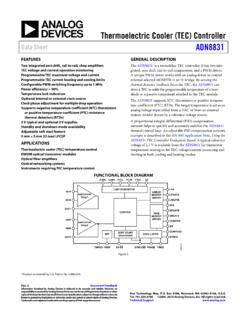
6 Available packages are: D (D-28) for all grades. E (E-28A) for J and K grades and /883B processed S, Tand U grades. N (N-28) for J, K, and L grades. P (P-28A) for PLCC in J, K grades. Example: AD574 AKN is K grade in plastic details on grade and package offerings screened in accordance with MIL-STD-883, refer to Analog Devices Military COMMONDCIDACIDAC =4 x N x IREF+5V SUPPLYVLOGICDATA MODE SELECT12/8 STATUSSTSDB11 MSBDB10DB9DB8DB7DB6DB5DB4DB3DB2DB1DB0 LSBDIGITALDATAOUTPUTSCHIP SELECTCSBYTE ADDRESS/SHORT CYCLEAOREAD/CONVERTR/CCHIP ENABLECE+12/+15V SUPPLYVCC+10V REFERENCEREF OUTANALOG COMMONACREFERENCE INPUTREF IN-12/-15V SUPPLYVEEBIPOLAR OFFSETBIP OFF10V SPAN INPUT10 VIN20V SPAN INPUT20 VINAD574A Block Diagram and Pin ConfigurationABSOLUTE MAXIMUM RATINGS*(Specifications apply to all grades, except where noted)VCC to Digital Common.
7 0 V to + VVEE to Digital Common .. 0 V to VVLOGIC to Digital Common .. 0 V to +7 VAnalog Common to Digital Common .. 1 VControl Inputs (CE, CS, AO 12/8, R/C) toDigital Common .. V to VLOGIC + VAnalog Inputs (REF IN, BIP OFF, 10 VIN) toAnalog Common .. VEE to VCC20 VIN to Analog Common .. 24 VREF OUT .. Indefinite Short to CommonMomentary Short to VCCChip Temperature .. 175 CPower Dissipation .. 825 mWLead Temperature (Soldering, 10 sec).. +300 CStorage Temperature (Ceramic) .. 65 C to +150 C(Plastic) .. 25 C to +100 C*Stresses above those listed under Absolute Maximum Ratings may causepermanent damage to the device.
8 This is a stress rating only and functionaloperation of the device at these or any other conditions above those indicated in theoperational sections of this specification is not implied. Exposure to absolutemaximum rating conditions for extended periods may affect device B 5 DEFINITIONS OF SPECIFICATIONSLINEARITY ERRORL inearity error refers to the deviation of each individual codefrom a line drawn from zero through full scale . The pointused as zero occurs 1/2 LSB ( mV for 10 volt span) be-fore the first code transition (all zeros to only the LSB on ).
9 Full scale is defined as a level 1 1/2 LSB beyond the last codetransition (to all ones). The deviation of a code from the truestraight line is measured from the middle of each AD574AK, L, T, and U grades are guaranteed for maxi-mum nonlinearity of 1/2 LSB. For these grades, this meansthat an analog value which falls exactly in the center of a givencode width will result in the correct digital output code. Valuesnearer the upper or lower transition of the code width may pro-duce the next upper or lower digital output code. The AD574 AJand S grades are guaranteed to 1 LSB max error.
10 For thesegrades, an analog value which falls within a given code widthwill result in either the correct code for that region or eitheradjacent that the linearity error is not LINEARITY ERROR (NO MISSINGCODES)A specification which guarantees no missing codes requires thatevery code combination appear in a monotonic increasing se-quence as the analog input level is increased. Thus every codemust have a finite width. For the AD574AK, L, T, and Ugrades, which guarantee no missing codes to 12-bit resolution,all 4096 codes must be present over the entire operating tem-perature ranges.