Transcription of AN-686 APPLICATION NOTE - Analog Devices
1 AN-686 . APPLICATION NOTE. One Technology Way Box 9106 Norwood, MA 02062-9106 Tel: 781/329-4700 Fax: 781/326-8703 Implementing an I2C Reset By Jim Greene The I2C bus is a high integrity, robust serial bus used for state. It is the only method of ending a transmission after control purposes in many systems. The primary compo- the reception of a byte. nents that make up a system are at least one master and Byte Width all bytes are 8 bits wide, with no exceptions. one slave. Under normal conditions, everything works fine; however, it is the abnormal conditions that gener- Message Length technically there is no maximum length ate problems. Two questions present themselves when a for a message; a minimum message consists of 2 bytes problem arises: Is the problem device or system related, (an address and a data byte).
2 Or some combination of both? What, if anything, can be Wait State this condition is rarely used, but is worth done about it? understanding. Once the SCL line is low, a device may Hard device failures are relatively easy to isolate. Perhaps continue to hold it low to identify a wait state. The wait a function does not work, proper power cycling does not state permits slow Devices to not lose synchronization resolve the issue, pins are stuck high or low, and so on. with the transmitting device. An example is writing many System related problems sometimes disguise themselves bytes to an E2 PROM; another is a processor holding off as device failures, or worse, are intermittent. It is the latter data from a slave to handle an interrupt. area that this APPLICATION note examines because it repre- Acknowledge The ACK is the condition under which sents the majority of bus fault conditions.
3 The master generates a 9th clock pulse on the SCL line Perhaps a brief description of the I2C bus is in order. The (for each byte) while the receiving device pulls the SDA. I2C (inter integrated circuit) bus was developed and pat- line low in order to signify that the last byte was received. ented by Philips. It allows Devices to communicate over A NAK is only generated by the master; it signals the an open-drain (or open-collector) 2-wire serial bus. Inter- slave that no additional data need be sent. A NAK is used facing is simple; serial data (SDA) and serial clock (SCL) prior to a STOP to prevent the slave from driving the bus are the only signals that traverse the circuit board. Due to with additional data when the master is about to termi- the low speed (literally dc to 400 kB/s) problems associ- nate the communication.
4 Ated with routing, transmission line effects and matching Frequently the master, which is usually a microcontroller are nonexistent. The limiting factor is bus capacitance, or a gate array, will be interrupted in the middle of its which is limited to 400 pF. communication with an I2C slave and, upon return, find The following terms are used to describe the I2C bus: a stuck bus. Initially this looks like a device problem, but it is not. The slave is still waiting to send the remainder Master the device that initiates a message, and defines of the data requested by the master. The problem is that the direction of the I2C bus. The master is also responsible the master has forgotten where it was when it was inter- for the generation of the clock (SCL). (9 clocks per byte: 8.)
5 Rupted or reset. An extraneous reset on the processor will for data and 1 for the acknowledge.). generally create this condition, especially if the processor Slave a device with an address that is addressed by a cannot save its status. At this point, the slave will have master. put the next bit out on the SDA line (because the SCL line may have dropped to a low on reset) and awaits the next Start a bus condition in which the SCL line is high and clock on SCL. Of course the processor does not send it, the SDA line transitions from a high to a low. It is the and as a result this slave just waits and waits. If the bit first operation on the bus and is always followed by an the slave puts on the SDA line is a 0, the newly awakened address. The least significant bit determines the direc- processor sees what appears to be a hung bus.
6 The bus tion of the bus. A high tells the slave that the bus will is in a nonoperational mode; however, it is not due to the read, while an LSB = 0 identifies a write to the specified slave. It is the processor's fault for not finishing the mes- address. sage it started. Generating graceful resets is not within Stop the condition opposite Start, under which the SCL the scope of this APPLICATION note. line is high while the SDA line goes from a low to a high REV. 0. AN-686 . What should you do? The slave must be permitted to fin- Solution 2: Adding a Reset Pin to an I2C Slave ish sending this last byte or be reset externally. Another method will reset the I2C slave. One function never seen on an I2C slave is a reset pin. To remedy this Solution 1: Clocking Through the Problem type of problem, a reset function is added via additional The first solution (letting the slave finish) requires hardware: an Analog switch.
7 The Analog switch needs no additional hardware because it is implemented in several attributes to perform the reset function properly. software. Note that while this method is very effective, E04536 0 12/03(0). The ADG749 fills the requirements: it may not be possible to clear a hung bus on every manufacturer's device all the time. (The design of the Small package: the SC70 requires less than 5 square I2C state machine will determine the effectiveness of the mm of board space clocking approach.). SPDT switch with break-before-make action The method is quite simple. It is the master's job to recover Very low on resistance: at 5 V and at 3 V. the bus and restore control to the main program. When the master detects the SDA line stuck in the low state, it Excellent on resistance flatness (allows repeatable merely needs to send some additional clocks and gener- resets in digital Devices ).
8 Ate a STOP condition. How many clocks will be needed? At 1 A of supply current, the power budget is not The number will vary with the number of bits that remain affected to be sent by the slave. The maximum would be 9. This number is derived from the worst-case scenario, the case The diagram below shows how the ADG749 can provide a where the processor was reset just after sending an ACK reset to an I2C slave device. When a reset to the slave must to the slave. Now the slave is ready to send 8 data bits and occur, the processor sends a logic low to the control pin receive 1 ACK (or NAK in the case of a bus recovery). on the Analog switch now labeled RESET (see diagram). The low going reset pulse must be of sufficient width to The procedure is as follows: permit the switch to discharge the decoupling capacitors 1) Master tries to assert a Logic 1 on the SDA line and internal circuitry.
9 The ADG749 is capable of generat- ing a reset to many I2C Devices with their associated 2) Master still sees a Logic 0 and then generates a clock decoupling capacitors. Testing has shown that a 15 s pulse on SCL (1-0-1 transition). reset pulse will switch the VDD line of 2 slaves and 1 F of 3) Master examines SDA. If SDA = 0, go to Step 2; if capacitance to within V of ground in <10 s. The turn SDA = 1, go to Step 4 on time is equally impressive at <5 s, which means that the I2C state machine will reset itself on power up. 4) Generate a STOP condition With an operational voltage range of V to V, the Note that this process may need to be repeated because ADG749 permits literally any I2C device to be reset by the the cleared SDA line may have been cleared for the next processor.
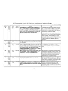
10 Analog Devices has other Analog switches if bit, which was a 1. There may be some concern about the level translation functions are required. effect this additional clocking and STOP ping has on other peripherals. There is no adverse effect; other slaves are ADG749. not paying attention due to the fact that they have not I2C DEVICE. S2. VDD. D. been addressed. Only the slave that had the interrupted VDD GND. S1. message will respond to the clocks. GND. RESET. This procedure is useful in the system code to help re- store the bus in the event that an SDA = 0 bus fault is NOTE: SWITCH SHOWN WITH RESET = LOGIC 1. encountered, regardless of the reason. Figure 1. Simple Interface Resets I 2C Bus Purchase of licensed I2C components of Analog Devices or one of its sublicensed Associated Companies conveys a license for the purchaser under the Philips I2C.