Transcription of an Single DCM Isolated Regulated DC-DC Converter
1 AN:029 Page 1 IntroductionThe DCM DC-DC Converter Module encapsulates isolation, regulation, thermal management, and fault monitoring in a Single module. Its wide input voltage range, high output power, high density, and high efficiency enable its use in a variety of industrial and military applications. The DCM is offered in two different packages: Converter housed in Package (ChiP) and Vicor Integrated Adapter (VIA) package, which delivers high power density through its superior thermal performance. This application note mainly focuses on ChiP based DCM. ChiP platform products use advanced magnetic structures that are integrated within high density interconnect (HDI) substrates, together with power semiconductors, control ASICs and a microcontroller.
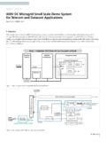
2 For more information on DCM capabilities and options, please see the Vicor web page for DCM operates on the same high frequency, double-clamped zero voltage switching (DC-ZVS) topology as the Vicor PFM and the PI31xx Isolated DC-DC Converter Modules. The DC-ZVS topology provides a revolutionary increase in density and efficiency compared to other complete DC-DC Converter CircuitryReferring to Figure 1, the DCM simplifies the design of the input, output, and control 1 Non- Isolated Point-of-Load RegulatorR1L1C1L2 CLOADTRENFT+IN +OUT-IN -OUTDCMLoad 2F1 Figure 1 Block Diagram of a Single DCM CircuitSingle DCM as an Isolated , Regulated DC-DC ConverterAPPLICATION NOTE | AN.
3 029 Arthur RussellApplications EngineerIntroduction 1 Support Circuitry 1 Input Circuitry 2 Control Pins 3 Light Load Boosting 5 Output Circuitry 5 Output Capacitor 5 Thermal Considerations 6 Layout and Routing 6 Conclusion 6 Contents Page AN:029 Page 2 Input CircuitryDCMs feature on-board protection for input overvoltage and overcurrent, so the fuse F1 shown in Figure 1 is only needed for applications that must pass safety approvals, such as CE Mark or UL60950. For more information on fuse selection and recommendations, refer to the data sheet for the DCM model of effective input impedance of the DCM is VIN2/PIN.
4 This form of the equation is the most relevant because for a given load, the DCM presents a constant power load to its input power source (up to the control loop bandwidth, which is up to 20kHz).To guarantee stability of the DCM control loop, the impedance of the source that supplies VIN must be less than the effective input impedance of the DCM at the expected minimum input line condition, over the control loop bandwidth. If the source cannot satisfy this requirement alone, the input filter circuit must compensate for the excessive impedance. A large electrolytic capacitor can be used: for example, at least 1000 F is recommended for a 320W DC-DC Converter operating with line voltages down to 16V, such as the DCM3623T50M31C2M00 (model specific values are provided in the corresponding DCM data sheet).
5 However, in cost-sensitive or space-limited applications, a more efficient solution may be possible. The theory behind the input impedance requirement is given in the Vicor tech an additional optimization to minimize ringing and provide additional margin between the DCM s rated low line and its input undervoltage fault protection threshold (UVLO), the source impedance of VIN should be further limited to be no more than 1/10 the effective input impedance of the the application circuit is designed such that the DCM is not inhibited using the EN pin, the DCM output voltage will become active during the input voltage ramp, when it reaches the input undervoltage fault protection (UVLO) voltage VIN-UVLO+.
6 The input filter needs to be designed according to this extreme low line condition. As the DCM starts near UVLO+, the source impedance must be low enough that input voltage transients caused by inrush current do not trigger efficiency is slightly impacted by high frequency ripple voltage developed on the DCM input due to switching currents. Ceramic input filter capacitors in close proximity to the +IN and IN leads can form a resonant tank with the package lead inductance and the internal input capacitors. When the DCM is operating near its maximum switching frequency (approximately 1 MHz), the resonant tank can amplify ringing voltage, leading to a slight increase in losses within the DCM.
7 This effect can be minimized by avoiding the placement of ceramic capacitors directly across the DCM input, or by reducing the Q of this resultant resonant tank by adding resistors in series with those on the design of the input filter can be found in the following application note, which emphasizes designing DC-DC converters for low EMI: supplies a design tool to assist the user in designing a stable filter, with minimal AN:029 Page 3 Control PinsThe three DCM control pins are EN, TR and FT. Internally, they are implemented as GPIOs, each with a pull-up resistor to a constant rail.
8 Each control pin has a simple internal bias and drive structure, which is maintained throughout the various operating modes. The logic thresholds, bias levels and bias strengths for the input pins do not change during startup or fault protection conditions. In general, the control pins can all be left unconnected to select their default is a digital input that enables the powertrain. The powertrain is disabled when EN is less than the EN disable threshold and enabled when EN is pulled above its enable threshold; if EN is left open, an internal 10k pull-up resistor keeps the powertrain selects the trim mode and sets the trimmed output voltage of the DCM.
9 The TR pin is sampled one time at power-up, after VIN exceeds VIN-UVLO+; its voltage at that time determines the function of TR for as long as the DCM is supplied an input voltage. If TR is greater than VTRIM-DIS when it is sampled, the DCM will be in non-trim mode. This is the case when TR is left open: an internal 10k pull-up resistor pulls TR up to VCC, selecting the non-trim mode of operation. In this mode, the programmed trim condition will simply be the rated nominal Vout of the DCM TR is sampled below VTRIM-DIS at power-up, the internal trim circuitry will be enabled and TR will control the output voltage setting as long as VIN is applied.
10 If the powertrain is disabled with EN or stopped by a fault condition, it retains the trim mode which was previously latched in when it resumes operation. The trim mode is re-evaluated only after removing and reapplying the input voltage to the nominal relationship between a trim resistor and the trim pin voltage is given by: A sample circuit to control TR is shown in Figure -IN connectionOutput VoltageReference,Current LimitReferenceand Soft Start ControlFigure 2 Example of a Circuit to Set TRVTR = VCC RTRIM / (RTRIM + 10k ) AN:029 Page 4 When trim mode is active, the programmed VOUT of the DCM maps linearly to the TR pin voltage.