Transcription of PSFB Quarter Brick DC/DC Converter Reference …
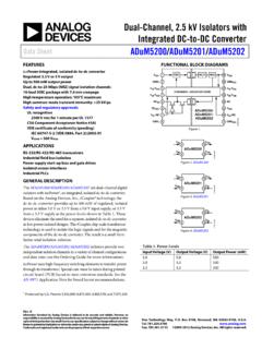
1 2010 Microchip Technology 1AN1335 ABSTRACTThis application note provides the digital implementa-tion of a telecom input 36 VDC-76 VDC to output 12 VDC,200W Quarter Brick DC/DC Brick Converter using thePhase-Shifted Full-Bridge (PSFB) topology. This topol-ogy combines the advantages of Pulse-WidthModulation (PWM) control and resonant dsPIC33F GS family series of Digital Signal Con-trollers (DSCs) was introduced by Microchip Technol-ogy Inc., to digitally control Switched Mode PowerConverters. The dsPIC33F GS family of devices con-sists of an architecture that combines the dedicatedDigital Signal Processor (DSP) and a devices support all of the prominent power con-version technologies that are used today in the powersupply addition, the dsPIC33F GS family of devices con-trols the closed loop feedback, circuit protection, faultmanagement and reporting, soft start, and output volt-age sequencing.
2 A DSC-based Switched Mode PowerSupply (SMPS) design offers reduced componentcount, high reliability and flexibility to have modularconstruction to reuse the designs. Selection of periph-erals such as the PWM module, Analog-to-Digital Con-verter (ADC), Analog Comparator, Oscillator andcommunication ports are critical to design a goodpower supply. MATLAB based simulation results arecompared to the actual test results and are discussedin subsequent , Intermediate Bus Converters (IBCs) havebecome popular in the telecom power supply telecom and data communication systems con-tain ASIC, FPGAs and integrated high-end systems require higher currents at multiple low-level voltages with tight load regulations.
3 Traditionally,bulk power supplies deliver different load voltages. Inthe conventional Distributed Power Architecture (DPA),the front-end AC/DC power supply generates 24V/48 Vand an individual isolated Brick Converter supports therequired low system voltages. These systems becomeinefficient and costly where very low voltages arerequired. In the Intermediate Bus Architecture (IBA),the IBC generates 12V/5V. Further, these voltages arestepped down to the required load voltages by Point ofLoads (PoLs).In IBA, the high-density power converters, IBC andPoLs are near to the load points, which bring consider-able financial gains with the improved these converters are at the load points, PCBdesign will be simpler with reduction in Interference (EMI) is also consider-ably reduced due to minimum routing length of highcurrent tracks.
4 Due to the position of these converters,the transient response is good and the system perfor-mance is improved. Modern systems require voltagesequencing, load sharing between the converters,external communication and data Switched Mode Power Supplies aredesigned with Analog PWM control to achieve therequired regulated outputs, and an additional microcon-troller performs the data communication and loadsequencing. To maximize the advantages of IBC, theconverter must be designed with reduced componentcount, higher efficiency, and density with lower requirements can be achieved by integrating thePWM controller, communication and load sharing withthe single intelligent controller.
5 The dsPIC33F GS fam-ily series of DSCs have combined these design featuresin a single chip that is suitable for the bus of the topics covered in this application noteinclude: DC/DC power module basics Topology selection for the Quarter Brick DC/DC Converter DSC placement choices and mode of control Hardware design for the isolated PSFB Quarter Brick DC/DC Converter Planar magnetics design Digital PSFB Quarter Brick DC/DC Converter design Digital control system design Digitally controlled load sharing MATLAB modeling Digital nonlinear control techniques Circuit schematics and laboratory test results Test demonstrationAuthor.
6 Ramesh Kankanala Microchip Technology Full-Bridge (PSFB) Quarter Brick DC/DC Converter Reference Design Using a dsPIC DSCAN1335DS01335A-page 2 2010 Microchip Technology 1:DISTRIBUTED POWER ARCHITECTURE (DPA)FIGURE 2:INTERMEDIATE BUS ARCHITECTURE (IBA)AC/DC Power SupplyDC/DC Brick ConverterDC/DC Brick ConverterDC/DC Brick VDC1. 8 VDCLoad Isolation Barrier24V/48V BusIsolation BarrierIntermediate Bus Converter (IBC)PoLPoLPoLPoLPoLPoLPoL = Point of LoadAC/DC Power 24V/48V VDCLoadLoadLoadLoadLoadLoad12V/5V BusSupply 2010 Microchip Technology 3AN1335 Quarter Brick CONVERTERThe Distributed-Power Open Standards Alliance(DOSA) defines the specifications for the single outputpin Quarter Brick DC/DC Converter .
7 These specifica-tions are applicable to all Quarter Bricks (unregulated,semi-regulated and fully regulated) for an outputcurrent range up to AC/DC Converter output is 48V in the IBA. Thisvoltage is further stepped down to an intermediate volt-age of 12V by an isolated IBC. This voltage is furtherstepped down to the required low voltage using Quarter Brick DC/DC converters are offered inthrough-hole configurations advantages of the Quarter Brick Converter are: Improved dynamic response Highest packaging density Improved Converter efficiency Isolation near the load end Output voltage ripple below the required limit DC/DC POWER MODULES BASICSB efore discussing the design aspects of the QuarterBrick Converter , the following requirements should beunderstood.
8 Input Capacitance Output Capacitance Remote ON/OFF Control Ripple and Noise Remote Sense Forced Air Cooling Overvoltage OvercurrentInput CapacitanceFor DC/DC converters with tight output regulationrequirements, it is recommended to use an electrolyticcapacitor of 1 F/W output power at the input to theQuarter Brick Converter . In the Quarter Brick Converterdesigns, these capacitors are external to the CapacitanceTo meet the dynamic current requirements and theoutput voltage regulations at the load end, additionalelectrolytic capacitors must be added. As a designguideline, in Quarter Brick Converter designs, 100 F/Ato 200 F/A of output current can be added and an effec-tive lower Equivalent Series Resistance (ESR) can beachieved by using a number of capacitors in ON/OFF ControlRemote ON/OFF control is used to enable or disablethe DC/DC Converter through an external control sig-nal.
9 The most common method to enable or disable theconverter is from the primary side (input side). Becausethe controller exists in the secondary side of the iso-lated barrier, an isolation circuit must be used to trans-fer the signal from the primary side to the secondaryside. This can be achieved using the opto-isolator,which is illustrated in Figure 3:REMOTE ON/OFFR ipple and NoiseThe output of a rectifier consists of a DC componentand an AC component. The AC component, alsoknown as ripple, is undesirable and causes pulsationsin the rectifier output. Ripple is an artifact of the powerconverter switching and filtering action, and has a fre-quency of some integral multiple of the power converteroperating switching occurs at multiples of the power converterswitching frequency, and is caused by a quick chargeand discharge of the small parasitic capacitances in thepower Converter operations.
10 Noise amplitude dependshighly on load impedance, filter components and themeasurement SenseRemote sense can be used to compensate voltagedrop in the set voltage when long traces/wires are usedto connect the load. In applications where remote sens-ing is not required, the sense pins can be connected tothe respective output ON/OFF (I/P)+ ANAS ignal to DSCCDIG_GNDR emote ON/OFFCRRAN1335DS01335A-page 4 2010 Microchip Technology Air CoolingTo remove heat from the high density board mountpower supplies, forced air cooling is applied using air cooling greatly reduces the required PCBsize and heat sink.