Example: bachelor of science
ATmega128A datasheet summary - Microchip Technology
mode stops the CPU while allowing the SRAM, Timer/Counters, SPI port, and interrupt system to continue functioning. The Power-down mode saves the register contents but freezes the Oscillator, disabling all other chip functions until the next interrupt or Hardware Reset. In Power-save mode, the
Tags:
Information
Domain:
Source:
Link to this page:
Documents from same domain

Power Factor Correction in Power Conversion …
ww1.microchip.com© 2007 Microchip Technology Inc. DS01106A-page 2 AN1106 FIGURE 1: CURRENT WAVEFORMS WITH AND WITHOUT PFC These waveforms illustrate that …

2.7V to 5.5V Single Supply CMOS Op Amp
ww1.microchip.comMCP601/1R/2/3/4 DS21314G-page 2 © 2007 Microchip Technology Inc. 1.0 ELECTRICAL CHARACTERISTICS Absolute Maximum Ratings † VDD –VSS.....7.0V

Data Encryption Routines for PIC24 and dsPIC Device
ww1.microchip.com© 2006 Microchip Technology Inc. DS01044A-page 1 AN1044 INTRODUCTION Currently, there are three data encryption standards approved …

Using SAM-BA for Linux on SAMA5D3 Xplained
ww1.microchip.comAN-8995 – Using SAM-BA for Linux on SAMA5D3 Xplained: 42328A−06/2014 Page 5 of 19 2. Setup With Ubuntu distributions, a user has to be member of the dialout group to access serial devices like

MCP6021/1R/2/3/4 - Rail-to-Rail Input/Output, 10 …
ww1.microchip.com2001-2017 Microchip Technology Inc. DS20001685E-page 1 MCP6021/1R/2/3/4 Features • Rail-to-Rail Input/Output • Wide Bandwidth: 10 MHz (typical)

Low Quiescent Current LDO - Microchip Technology
ww1.microchip.com2005-2016 Microchip Technology Inc. DS20001826D-page 1 MCP1700 Features: • 1.6 µA Typical Quiescent Current • Input Operating Voltage Range: 2.3V to 6.0V

MCP1703 250 mA, 16V, Low Quiescent Current
ww1.microchip.com2010 Microchip Technology Inc. DS22049E-page 1 MCP1703 Features: • 2.0 µA Typical Quiescent Current • Input Operating Voltage Range: 2.7V to16.0V

MTCH6102 Low-Power Projected Capacitive Touch …
ww1.microchip.com2014 Microchip Technology Inc. DS40001750A-page 1 Description: Microchip’s MTCH6102 is a turnkey projected capacitive touch controller that simplifies adding

PIC32 GUI Development Board with Projected …
ww1.microchip.comPIC32 GUI Development Board with Projected Capacitance (PCAP) Touch Information Sheet Microchip Technology Inc.

RN4020 Bluetooth Low Energy Module User’s Guide
ww1.microchip.comRN4020 BLUETOOTH LOW ENERGY MODULE USER’S GUIDE 2014 Microchip Technology Inc. DS70005191B-page 7 Preface INTRODUCTION This chapter contains general information that will be useful to know before using the
Related documents

LAB EXERCISE 7.1 UP/DOWN Counters Objectives Materials
www.csun.eduUse PB2 as the clock input, Ll and L2 as the 1 and 2 outputs. ... We will study both up and down counters. LD-2 Logic Designer : 74LS76 Dual J-K Flip-flops with Preset and Clear . Jumper Wires . TIL Data Book . Procedure . 1. Place a 74LS76 on the LD-2 breadboard and wire the
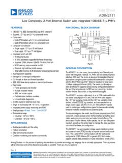
Data Sheet ADIN2111 - analog.com
www.analog.comDec 18, 2021 · Port dedicated statistics counters Link and cable diagnostics 25 MHz crystal or external clock input Single or dual supply with 1.8 V or 3.3 V operation Integrated power supply monitoring and POR Small package: 48-lead, 7 mm × 7 mm LFCSP Temperature range Industrial: −40°C to +85°C Extended: −40°C to +105°C APPLICATIONS

CD54/74HC192, CD54/74HC193, CD54/74HCT193 datasheet …
www.ti.comCLOCK UP CLOCK DOWN RESET PARALLEL LOAD FUNCTION ↑ H L H Count Up H ↑ L H Count Down X X H X Reset X X L L Load Preset Inputs H = High Voltage Level, L = Low Voltage Level, X = Don’t Care,↑= Transition from Low to High Level ASYN. MASTER CLOCK UP 11 14 5 4 15 1 10 9 3 6 7 12 13 Q0 Q1 Q2 Q3 TERMINAL P0 P1 P2 P3 LOAD CLOCK DOWN 2 …

SN54/74LS192 SN54/74LS193 PRESETTABLE BCD/DECADE …
ece-classes.usc.eduUP/DOWN COUNTER The SN54/74LS192 is an UP/DOWN BCD Decade (8421) Counter and the SN54/74LS193 is an UP/DOWN MODULO-16 Binary Counter. Separate Count Up and Count Down Clocks are used and in either counting mode the circuits operate synchronously. The outputs change state synchronous with the LOW-to-HIGH transitions on the clock inputs.

Design, Implementation and Simulation of 24h Digital Clock ...
infinite-vigilant.github.ioelectromechanical clock, it uses digital counters that count second, minute and hours. Each sixty seconds make a minute and each sixty minutes an hour connected to the output of the. After twenty four hours the clock resets and starts from initial condition. The functional unit of a digital clock is a counter that represents a second, minute or ...
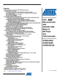
AT90CAN32 AT90CAN64 AT90CAN128 - Microchip Technology
ww1.microchip.comThe Idle mode stops the CPU while allowing the SRAM, Timer/Counters, SPI/CAN ports and interrupt system to continue functioning. The Power-down mode saves the register contents but freezes the Oscillator, disabling all other chip functions until the next interrupt or Hardware Reset.

Datasheet - Nuvoton
www.nuvoton.com– Two 16-bit Timers/Counters 0 and 1 compatible with standard 8051. – One 16-bit Timer 2 with three-channel input capture module and 9 input pin can be selected. – One 16-bit auto-reload Timer 3, which can be the baud rate clock source of UARTs. – …
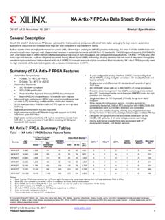
XA Artix-7 FPGAs Data Sheet: Overview (DS197)
www.xilinx.comGlobal Clock Lines In each 7 series FPGA, 32 global clock lines have the highest fanout and can reach every flip-flop clock, clock enable, and set/reset, as well as many logic inputs. There are 12 global cl ock lines within any clock region driven by the horizontal clock buffers (BUFH).

ATmega328/P datasheet summary
datasheet.octopart.com8-bit Timer/Counters 2 16-bit Timer/Counters 1 and support a real Read-While-Write Self-Programming mechanism. There is a separate Boot Loader Section, and the SPM instruction can only execute from there. In , there is no Read-While-Write support and no separate Boot Loader Section. The SPM instruction can execute from the entire Flash.