Transcription of Data Sheet ADP1763 - Analog Devices
1 3 A, Low VIN, Low Noise, CMOS Linear Regulator Data Sheet ADP1763 Rev. D Document Feedback Information furnished by Analog Devices is believed to be accurate and reliable. However, no responsibility is assumed by Analog Devices for its use, nor for any infringements of patents or other rights of third parties that may result from its use. Specifications subject to change without notice. No license is granted by implication or otherwise under any patent or patent rights of Analog Devices . Trademarks and registered trademarks are the property of their respective owners. One Technology Way, Box 9106, Norwood, MA 02062-9106, : 2016 2020 Analog Devices , Inc.
2 All rights reserved. Technical Support FEATURES 3 A maximum output current Low input voltage supply range VIN = V to V, no external bias supply required Fixed output voltage range: VOUT_FIXED = V to V Adjustable output voltage range: VOUT_ADJ = V to V Ultralow noise: 2 V rms, 100 Hz to 100 kHz Noise spectral density 4 nV/ Hz at 10 kHz 3 nV/ Hz at 100 kHz Low dropout voltage: 95 mV typical at 3 A load Operating supply current: mA typical at no load fixed output voltage accuracy over line, load, and temperature Excellent power supply rejection ratio (PSRR) performance 59 dB typical at 10 kHz at 3 A load 43 dB typical at 100 kHz at 3 A load Excellent load/line transient response Soft start to reduce inrush current Optimized for small 10 F ceramic capacitors Current-limit and thermal overload protection Power-good indicator Precision enable 16-lead, 3 mm 3 mm LFCSP package APPLICATIONS Regulation to noise sensitive applications such as radio frequency (RF) transceivers, Analog -to-digital converter (ADC) and digital-to- Analog converter (DAC)
3 Circuits, phase-locked loops (PLLs), voltage controlled oscillators (VCOs) and clocking integrated circuits Field-programmable gate array (FPGA) and digital signal processor (DSP) supplies Medical and healthcare Industrial and instrumentation GENERAL DESCRIPTION The ADP1763 is a low noise, low dropout (LDO) linear regulator. It is designed to operate from a single input supply with an input voltage as low as V without the requirement of an external bias supply to increase efficiency and provide up to 3 A of output current. The low 95 mV typical dropout voltage at a 3 A load allows the ADP1763 to operate with a small headroom while maintaining regulation and providing better efficiency.
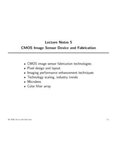
4 The ADP1763 is optimized for stable operation with small 10 F ceramic output capacitors. The ADP1763 delivers optimal transient performance with minimal board area. TYPICAL APPLICATION CIRCUITS VINENSSVREGVOUTSENSECOUT10 FPGRPULL-UP100k PGVADJGNDREFCAPCIN10 FONOFF12923-001 VOUT = = FCREF1 FCSS10nF Figure 1. Fixed Output Operation VINENSSVREGVOUTSENSEPGRPULL-UP100k PGVADJGNDREFCAPCREG1 FCREF1 FRADJ10k CSS10nFONOFF12923-002 VOUT = = FCIN10 F Figure 2. Adjustable Output Operation Table 1. Related Devices Device Input Voltage Maximum Current Fixed/ Adjustable Package ADP1761 V to V 1 A Fixed/adjustable 16-lead LFCSP ADP1762 V to V 2 A Fixed/adjustable 16-lead LFCSP ADP1740/ADP1741 V to V 2 A Fixed/adjustable 16-lead LFCSP ADP1752/ADP1753 V to V A Fixed/adjustable 16-lead LFCSP ADP1754/ADP1755 V to V A Fixed/adjustable 16-lead LFCSP The ADP1763 is available in fixed output voltages ranging from V to V.
5 The output of the adjustable output model can be set from V to V through an external resistor connected between VADJ and ground. The ADP1763 has an externally programmable soft start time by connecting a capacitor to the SS pin. Short-circuit and thermal overload protection circuits prevent damage in adverse conditions. The ADP1763 is available in a small 16-lead LFCSP package for the smallest footprint solution to meet a variety of applications. ADP1763 Data Sheet Rev. D | Page 2 of 19 TABLE OF CONTENTS Features .. 1 Applications .. 1 General Description .. 1 Typical Application Circuits .. 1 Revision History .. 2 Specifications.
6 3 Input and Output Capacitor: Recommended Specifications . 4 Absolute Maximum Ratings .. 5 Thermal Data .. 5 Thermal Resistance/Parameter .. 5 ESD 5 Pin Configuration and Function Descriptions .. 6 Typical Performance Characteristics .. 7 Theory of Operation .. 11 Soft Start Function .. 11 Adjustable Output Voltage .. 12 Enable Feature .. 12 Power-Good (PG) Feature .. 12 Applications Information .. 14 Capacitor Selection .. 14 Undervoltage Lockout .. 15 Current-Limit and Thermal Overload Protection .. 15 Paralleling ADP1763 for High Current Applications .. 15 Thermal Considerations .. 16 PCB Layout Considerations .. 18 Outline Dimensions.
7 19 Ordering Guide .. 19 REVISION HISTORY 3/2020 Rev. C to Rev. D Changes to Thermal Data Section, Thermal Resistance/Parameter Section, and Table 5 .. 5 9/2017 Rev. B to Rev. C Change to Thermal Considerations Section .. 17 5/2017 Rev. A to Rev. B Change to Figure 19 Caption, Figure 20 Caption, and Figure 21 Caption .. 9 Change to Figure 22 Caption .. 10 Updated Outline Dimensions .. 18 9/2016 Rev. 0 to Rev. A Changes to Figure 23 and Figure 24 .. 11 4/2016 Revision 0: Initial Version Data Sheet ADP1763 Rev. D | Page 3 of 19 SPECIFICATIONS VIN = VOUT + V or VIN = V, whichever is greater, ILOAD = 10 mA, CIN = 10 F, COUT = 10 F, CREF = 1 F, CREG = 1 F, TA = 25 C, Minimum and maximum limits at TJ = 40 C to +125 C, unless otherwise noted.
8 Table 2. Parameter Symbol Test Conditions/Comments Min Typ Max Unit INPUT VOLTAGE SUPPLY RANGE VIN TJ = 40 C to +125 C V CURRENT Operating Supply Current IGND ILOAD = 0 A 8 mA ILOAD = 10 mA 8 mA ILOAD = 100 mA mA ILOAD = 3 A 12 16 mA Shutdown Current IGND-SD EN = GND 2 A TJ = 40 C to +85 C, VIN = (VOUT + V) to V 180 A TJ = 85 C to 125 C, VIN = (VOUT + V)
9 To V 800 A OUTPUT NOISE1 OUTNOISE 10 Hz to 100 kHz, VIN = V, VOUT = V 12 V rms 100 Hz to 100 kHz, VIN = V, VOUT = V 2 V rms 10 Hz to 100 kHz, VIN = V, VOUT = V 15 V rms 100 Hz to 100 kHz, VIN = V, VOUT = V 2 V rms 10 Hz to 100 kHz, VIN = V, VOUT = V 21 V rms 100 Hz to 100 kHz, VIN = V, VOUT = V 2 V rms Noise Spectral Density OUTNSD VOUT = V to V, ILOAD = 100 mA At 10 kHz 4 nV/ Hz At 100 kHz 3 nV/ Hz POWER SUPPLY REJECTION RATIO1 PSRR ILOAD = 3 A, modulated VIN 10 kHz, VOUT = V, VIN = V 59 dB 100 kHz, VOUT = V, VIN = V 43 dB 1 MHz, VOUT = V.
10 VIN = V 37 dB 10 kHz, VOUT = V, VIN = V 62 dB 100 kHz, VOUT = V, VIN = V 45 dB 1 MHz, VOUT = V, VIN = V 33 dB OUTPUT VOLTAGE Output Voltage Range TA = 25 C VOUT_FIXED V VOUT_ADJ V Fixed Output Voltage Accuracy VOUT ILOAD = 100 mA, TA = 25 C + % 10 mA < ILOAD < 3 A, VIN = (VOUT + V) to V, TJ = 0 C to 85 C 1 + % 10 mA < ILOAD < 3 A, VIN = (VOUT + V)