Transcription of FEATURES DESCRIPTIO U - analog.com
1 1LT1931/LT1931A1931fa Fixed Frequency Operation Very Low Noise: 1mVP-P Output Ripple 5V at 350mA from 5V Input 12V at 150mA from 5V Input Uses Small Surface Mount Components Wide Input Range: to 16V Low Shutdown Current: < 1 A Low VCESAT Switch: 400mV at 1A Pin-for-Pin Compatible with the LT1611 Low Profile (1mm) ThinSOTTM PackageThe LT 1931/LT1931A are the industry s highest powerinverting SOT-23 current mode DC/DC converters. Bothparts include a 1A integrated switch allowing high currentoutputs to be generated in a small footprint. The LT1931switches at while the LT1931A switches at high speeds enable the use of tiny, low costcapacitors and inductors 2mm or less in height.
2 TheLT1931 is capable of generating 5V at 350mA or 12 Vat 150mA from a 5V supply, while the LT1931A cangenerate 5V at 300mA using significantly smaller induc-tors. Both parts are easy pin-for-pin upgrades for higherpower LT1611 LT1931/LT1931A operate in a dual inductor invertingtopology that filters both the input side and output sidecurrent. Very low output voltage ripple approaching 1mVP-Pcan be achieved when ceramic output capacitors are frequency switching ensures a clean output freefrom low frequency noise typically present with chargepump solutions.
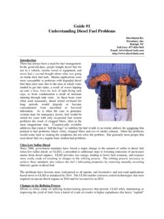
3 The low impedance output remains within1% of nominal during large load steps. The 36V switchallows VIN to VOUT differential of up to LT1931/LT1931A are available in the 5-lead ThinSOTpackage. Disk Drive MR Head Bias Digital Camera CCD Bias LCD Bias GaAs FET Bias Local Low Noise/Low Impedance Negative InvertingDC/DC Converters in ThinSOTF igure 1. 5V to 5V, 350mA Inverting DC/DC ConverterVINVIN5 VVOUT 5V350mA1931 F01 SWL1A10 HL1B10 HD1 GNDLT1931C1: TAIYO YUDEN X5R JMK212BJ475 MGC2: TAIYO YUDEN X5R LMK212BJ105 MGC3: TAIYO YUDEN X5R JMK325BJ226 MMD1: ON SEMICONDUCTOR MBR0520L1: SUMIDA FC322 FC21 CURRENT (mA)050 EFFICIENCY (%)55657075100851002002501931 TA016090958050150300350 EfficiencyFEATURESDESCRIPTIOUAPPLICATIO SUTYPICAL APPLICATIOU, LTC and LT are registered trademarks of Linear Technology Corporation.
4 ThinSOT is a trademark of Linear Technology Corporation. All other trademarks are the property of their respective Operating Operating Voltage1616 VFeedback Voltage Pin Bias CurrentVNFB = 48816 AQuiescent CurrentVSHDN = , Not Current in ShutdownVSHDN = 0V, VIN = AReference Line VIN Duty Cycle 84907582%Switch Current Limit(Note 3) VCESATISW = 1A400600400600mVSwitch Leakage CurrentVSW = ASHDN Input Voltage, Input Voltage, Pin Bias CurrentVSHDN = 3V16323570 AVSHDN = A(Note 1)VIN Voltage.
5 16 VSW Voltage .. to 36 VNFB Voltage .. 2 VCurrent Into NFB Pin .. 1mASHDN Voltage .. 16 VMaximum Junction Temperature .. 125 COperating Temperature Range (Note 2) .. 40 C to 85 CStorage Temperature Range .. 65 C to 150 CLead Temperature (Soldering, 10 sec) .. 300 CABSOLUTE AXI U RATI GSWWWUPACKAGE/ORDER I FOR ATIOUUWThe denotes specifications which apply over the full operating temperature range, otherwise specifications are TA = 25 = 3V, VSHDN = VIN, unless otherwise noted. (Note 2)ELECTRICAL CHARACTERISTICSNote 1: Absolute Maximum Ratings are those values beyond which the lifeof a device may be 2: The LT1931E/LT1931AE are guaranteed to meet performancespecifications from 0 C to 70 C.
6 Specifications over the 40 C to 85 Coperating temperature range are assured by design, characterization andcorrelation with statistical process controls. LT1931I/LT1931AI areguaranteed over the 40 C to 85 C temperature 3: Current limit guaranteed by design and/or correlation to static = 125 C, JA = 150 C/ WORDER PART NUMBERS5 PART MARKINGC onsult LTC Marketing for parts specified with wider operating temperature Options Tape and Reel: Add #TRLead Free: Add #PBF Lead Free Tape and Reel: Add #TRPBFLead Free Part Marking: 1 GND 2 TOP VIEWS5 PACKAGE5-LEAD PLASTIC TSOT-23 NFB 35 VIN4 SHDN3LT1931/LT1931A1931faTYPICAL PERFOR A CE CHARACTERISTICS UWQuiescent CurrentTEMPERATURE ( C) 50 QUIESCENT CURRENT (mA) SWITCHINGLT1931 ALT1931 TEMPERATURE ( C) 50 25025501931 G0275100 VOLTAGE (V)SHDN PIN VOLTAGE (V)0 10 SHDN PIN CURRENT ( A)10305012341931 G03570900204060806LT1931 ATA = 25 CLT1931 Feedback Pin VoltageShutdown Pin CurrentCurrent LimitSwitch Saturation VoltageOscillator FrequencyDUTY CYCLE (%)10 CURRENT LIMIT (A) = 25 CSWITCH CURRENT (A)
7 00 VCESAT (V) = 25 CTEMPERATURE ( C) (MHz) 25025501931 FU CTIO SSW (Pin 1): Switch Pin. Connect inductor/diode trace area at this pin to keep EMI (Pin 2): Ground. Tie directly to local ground (Pin 3): Feedback Pin. Reference voltage is resistive divider tap here. Minimize trace NFB bias current flows out of the pin. Set R1 and R2according to:For LTRVROUT1931 11 2551 25524106:|| .. =+()For LTA RVROUT193111 2551 25528106:|| .. =+()SHDN (Pin 4): Shutdown Pin. Tie to or more to enabledevice. Ground to shut (Pin 5): Input Supply Pin.
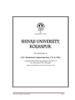
8 Must be locally DIAGRA WFigure 2 OPERATIOUThe LT1931 uses a constant frequency, current modecontrol scheme to provide excellent line and load regula-tion. Operation can be best understood by referring to theBlock Diagram in Figure 2. At the start of each oscillatorcycle, the SR latch is set, turning on the power switch voltage proportional to the switch current is added to astabilizing ramp and the resulting sum is fed into thepositive terminal of the PWM comparator A2. When thisvoltage exceeds the level at the negative input of A2, the SRlatch is reset, turning off the power switch.
9 The level at thenegative input of A2 is set by the error amplifier (gm) andis simply an amplified version of the difference betweenthe feedback voltage and the reference voltage of this manner, the error amplifier sets the correct peakcurrent level to keep the output in regulation. If the erroramplifier s output increases, more current is taken fromthe output; if it decreases, less current is taken. Onefunction not shown in Figure 2 is the current limit. Theswitch current is constantly monitored and not allowed toexceed the nominal value of If the switch currentreaches , the SR latch is reset regardless of the stateof comparator A2.
10 This current limit protects the powerswitch as well as various external components connectedto the Block Diagram for the LT1931A is identical except thatthe oscillator is and resistors R3 to R6 are one-halfthe LT1931 values. + + SWDRIVERCOMPARATOR2 SHUTDOWNSHDN41 + BDR680kR4150kR330kQ2x10Q1Q3R580kVINVIN5 NFBCPL(OPTIONAL)R2(EXTERNAL)R1(EXTERNAL) VOUTNFB3A2A1gm5LT1931/LT1931A1931faAPPLI CATIO S I FOR ATIOWUUULT1931A AND LT1931 DIFFERENCES:Switching FrequencyThe key difference between the LT1931A and LT1931 isthe faster switching frequency of the LT1931A.