Transcription of High-Accuracy, High-Side, Adjustable Current …
1 MIC2039 high - accuracy , high - side , Adjustable Current Limit power switch General Description The MIC2039 is a high - side MOSFET power distribution switch providing increased system reliability by using 5% Current -limit accuracy . The MIC2039 has an operating input voltage range from to , is internally Current limited, and has thermal shutdown to protect the device and system. The MIC2039 is offered with either active- high or active-low logic level enable input controls. It has an open drain fault status output flag with a built-in 32ms delay that asserts low during overcurrent or thermal-shutdown conditions.
2 The MIC2039 switches feature an Adjustable output Current limit that is resistor programmable from to The MIC2039 switch also offers a unique, Kickstart feature that allows momentary high - Current surges up to the secondary Current limit (ILIMIT_2nd) during startup or while operating in steady state. This is useful for charging loads with high inrush currents, such as capacitors. After an overcurrent condition is established, these switches enter into a constant Current -limit mode unless the die temperature exceeds the thermal-shutdown specification.
3 The MIC2039 is available in 6-pin SOT-23 and 6-pin 2mm 2mm thin DFN packages. The MIC2039 has an operating junction temperature range of 40 C to +125 C. Datasheets and support documentation are available on Micrel s web site at: Features 5% Current limit accuracy Input supply range from to Low quiescent Current : 100 A typical ( switch ON) 75m typical RDS(ON) at to Adjustable output Current Kickstart momentary secondary Current -limit threshold (120ms period) Soft-start functionality Undervoltage lockout (UVLO) Fast 10 s short-circuit response time (non-Kickstart options) Fault status output flag Logic-controlled enable (active- high , active-low)
4 Thermal shutdown Pin compatible with the MIC2009/MIC2019 6-pin 2mm 2mm thin DFN and 6-pin SOT-23 packages Junction temperature range from 40 C to +125 C Applications USB peripherals and USB compatible DTV/STB Notebooks and consumer electronics General-purpose power distribution Typical Application Micrel Inc. 2180 Fortune Drive San Jose, CA 95131 USA tel +1 (408) 944-0800 fax + 1 (408) 474-1000 December 8, 2014 Revision Micrel, Inc. MIC2039 Ordering Information Part Number Top Mark(1) Current Limit Enable Kickstart Package MIC2039 AYM6 39AA Adjustable Active high No SOT-23-6L MIC2039 BYM6 39BB Adjustable Active Low No SOT-23-6L MIC2039 AYMT 3A9 Adjustable Active high No 6-pin 2mm x 2mm Thin DFN(2) MIC2039 BYMT B39 Adjustable Active Low No 6-pin 2mm x 2mm Thin DFN(2) MIC2039 EYM6 39AE Adjustable Active high Yes SOT-23-6L MIC2039 FYM6 39AF Adjustable Active Low Yes SOT-23-6L MIC2039 EYMT D39 Adjustable Active high Yes 6-pin 2mm x 2mm Thin DFN(2)
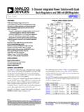
5 MIC2039 FYMT F39 Adjustable Active Low Yes 6-pin 2mm x 2mm Thin DFN(2) Note: 1. Under-bar symbol ( _ ) may not be to scale. 2. Thin DFN is a GREEN RoHS-compliant package. Lead finish is NiPdAu. Mold compound is Halogen Free. Pin Configuration SOT-23 6-pin (M6) Top View 2mm x 2mm 6-pin Thin DFN (MT)(3) (Top View) Notes: 3. Thin DFN = Pin 1 identifier. December 8, 2014 2 Revision Micrel, Inc. MIC2039 Pin Description Pin Number Pin Name Pin Function SOT-23-6L 6-Pin 2mm x 2mm Thin DFN 1 6 VIN Input: power switch and logic supply input. 2 5 GND Ground: Input and output return pin.
6 3 4 EN Enable (Input): Logic compatible, enable control input that allows switch turn-on/off. Do not leave the EN pin floating. 4 3 FAULT/ Fault Status Flag (Output): Active-low, open-drain output. A logic low state indicates an overcurrent or thermal shutdown condition. An overcurrent condition must last longer than tFAULT/ to assert FAULT/. A pull-up resistor (10k recommended) to an external supply is required. 5 2 ILIMIT Current Limit Set: Current limit adjust setting. Connect a resistor from this pin to GND to set the Current limit, but do not leave the ILIMIT pin floating.
7 6 1 VOUT switch Output: power switch output. EP ePad Exposed Pad: Exposed pad on bottom of package. Connect to electrical ground for optimum thermal dissipation. December 8, 2014 3 Revision Micrel, Inc. MIC2039 Absolute Maximum Ratings(4) VIN to GND .. to +6V VOUT to GND .. to +6V VILIMIT to GND .. to +6V VEN to GND .. to +6V VFAULT/ to GND .. to +6V FAULT/ Current (IFAULT/) .. 25mA Maximum power Dissipation (PD) .. Internally Limited Lead Temperature (soldering, 10s) .. 260 C Storage Temperature (TS) .. 65 C to +150 C ESD Rating(6) HBM .. 3kV MM.
8 300V Operating Ratings(5) Supply Voltage (VIN) .. + to + VEN, VFAULT/ .. to + VILIMIT, VOUT .. to VIN Junction Temperature (TJ) .. 40 C to +125 C Package Thermal Resistance SOT-23-6 ( JA) .. C/W 6-pin 2mm 2mm Thin DFN ( JA) .. 90 C/W Electrical Characteristics(7) VIN = VEN = 5V; CIN = 1 F; TJ = 25 C. Bold values indicate 40 C TA +85 C, unless noted. Symbol Parameter Condition Min. Typ. Max. Units power Supply Input VIN Input Voltage Range V VUVLO Input Supply Undervoltage Lockout Threshold VIN rising V VIN falling V VUVLOHYS Input Supply Undervoltage Lockout Threshold Hysteresis VIN rising or VIN falling 100 mV IDD Supply Current switch OFF (IOUT = 0A) Active- high Enable (A): VEN = 0V, VIN = 5V 5 A Active-low Enable (B): VEN = VIN = 5V switch ON (IOUT = 0A) Active- high Enable (A): VEN = , VIN = 5V 100 300 Active-low Enable (B).
9 VEN = 0V, VIN = 5V power MOSFET RDS(ON) switch On Resistance VIN = , IOUT = 350mA 100 177 m VIN = , IOUT = 350mA 85 145 VIN = 5V, IOUT = 350mA 75 125 ILKG Output Leakage Current switch Off, VOUT = 0V 15 A Notes: 4. Exceeding the absolute maximum ratings may damage the device. 5. The device is not guaranteed to function outside its operating ratings. 6. Devices are ESD sensitive. Handling precautions are recommended. Human body model, in series with 100pF. 7. Specification for packaged product only December 8, 2014 4 Revision Micrel, Inc. MIC2039 Electrical Characteristics(7) (Continued) VIN = VEN = 5V; CIN = 1 F; COUT = 1 F TJ = 25 C.
10 Bold values indicate 40 C TJ +125 C, unless noted otherwise. Symbol Parameter Condition Min. Typ. Max. Units Current Limit ILIMIT Current Limit (Resistor values are standard values) RLIMIT = 115 , VIN = 5V, VOUT = VIN A RLIMIT = 115 , VIN = , VOUT = 0V RLIMIT = 145 , VIN = 5V, VOUT = VIN RLIMIT = 287 , VIN = 5V, VOUT = VIN RLIMIT = 576 , VIN = 5V, VOUT = VIN RLIMIT = , VIN = 5V, VOUT = VIN ILIMIT_2nd Secondary Current Limit (Kickstart parts only) VOUT = 0V 6 A I/O VEN Enable Voltage Logic Low V Logic high IEN Enable Input Current 0V VEN 5V 1 A RFAULT/ FAULT/ Output Resistance IOUT = 10mA 25 IFAULT/_OFF FAULT/ Off Current VFAULT/ = VIN 10 A Thermal Protection TSD Thermal-Shutdown Threshold TJ rising 157 C TSDHYS Thermal-Shutdown Hysteresis 15 C Timing Specifications (AC Parameters) tRISE Output Turn-on Rise Time(8) RLOAD = 10 ; COUT = 1 F 700 s tFALL Output Turn-off Fall Time(8) VEN = OFF; RLOAD = 10 ; COUT = 1 F 32 s tON_DLY Output Turn-on Delay(8) RLOAD = 10.