Transcription of Integrated, Quad RF Transceiver with Observation Path …
1 Integrated, quad RF Transceiver with Observation path Data Sheet ADRV9026 Rev. C Document Feedback Information furnished by Analog Devices is believed to be accurate and reliable. However, no responsibility is assumed by Analog Devices for its use, nor for any infringements of patents or other rights of third parties that may result from its use. Specifications subject to change without notice. No license is granted by implication or otherwise under any patent or patent rights of Analog Devices. Trademarks and registered trademarks are the property of their respective owners. One Technology Way, Box 9106, Norwood, MA 02062-9106, Tel: 2019 2021 Analog Devices, Inc. All rights reserved. Technical Support 8 BFEATURES 4 differential transmitters 4 differential receivers 2 Observation receivers with 2 inputs each Center frequency: 75 MHz to 6000 MHz Maximum receiver bandwidth: 200 MHz Maximum transmitter large signal bandwidth: 200 MHz Maximum transmitter synthesis bandwidth: 450 MHz Maximum Observation receiver bandwidth.
2 450 MHz Fully integrated independent fractional-N radio frequency synthesizers Fully integrated clock synthesizer Multichip phase synchronization for all local oscillators and baseband clocks Support for TDD and FDD applications Gbps JESD204B/JESD204C digital interface 9 BAPPLICATIONS 3G/4G/5G TDD and FDD massive MIMO, macro and small cell base stations 10 BGENERAL DESCRIPTION The ADRV9026 is a highly integrated, radio frequency (RF) agile Transceiver offering four independently controlled transmitters, dedicated Observation receiver inputs for monitoring each transmitter channel, four independently controlled receivers, integrated synthesizers, and digital signal processing functions providing a complete Transceiver solution. The device provides the performance demanded by cellular infrastructure applications, such as small cell base station radios, macro 3G/4G/5G systems, and massive multiple in/multiple out (MIMO) base stations.
3 The receiver subsystem consists of four independent, wide bandwidth, direct conversion receivers with wide dynamic range. The four independent transmitters use a direct conversion modulator resulting in low noise operation with low power consumption. The device also includes two wide bandwidth, time shared, Observation path receivers with two inputs each for monitoring transmitter outputs. The complete Transceiver subsystem includes automatic and manual attenuation control, dc offset correction, quadrature error correction (QEC), and digital filtering, eliminating the need for these functions in the digital baseband. Other auxiliary functions such as analog-to- digital converters (ADCs), digital -to-analog converters (DACs), and general-purpose input/outputs (GPIOs) that provide an array of digital control options are also integrated. To achieve a high level of RF performance, the Transceiver includes five fully integrated phase- locked loops (PLLs).
4 Two PLLs provide low noise and low power fractional-N RF synthesis for the transmitter and receiver signal paths. A third fully integrated PLL supports an independent local oscillator (LO) mode for the Observation receiver. The fourth PLL generates the clocks needed for the converters and digital circuits, and a fifth PLL provides the clock for the serial data interface. A multichip synchronization mechanism synchronizes the phase of all LOs and baseband clocks between multiple ADRV9026 chips. All voltage controlled oscillators (VCOs) and loop filter components are integrated and adjustable through the digital control interface. The serial data interface consists of four serializer lanes and four deserializer lanes. The interface supports both the JESD204B and JESD204C standards, operating at data rates up to Gbps. The interface also supports interleaved mode for lower bandwidths, thus reducing the number of high speed data interface lanes to one.
5 Both fixed and floating-point data formats are supported. The floating-point format allows internal automatic gain control (AGC) to be invisible to the demodulator device. The ADRV9026 is powered directly from V, V, and V regulators and is controlled via a standard serial peripheral interface (SPI) serial port. Comprehensive power-down modes are included to minimize power consumption in normal use. The ADRV9026 is packaged in a 14 mm 14 mm, 289-ball chip scale ball grid array (CSP_BGA). ADRV9026 Data Sheet Rev. C | Page 2 of 131 12 BTABLE OF CONTENTS Features .. 1 Applications .. 1 General Description .. 1 Revision History .. 2 Functional Block Diagram .. 3 Specifications .. 4 Transmitters and 4 Synthesizers, Auxiliary Converters, and Clock References .. 11 digital Specifications .. 14 Power Supply Specifications .. 15 Current Consumption .. 16 digital Interface and Timing Specifications .. 17 Absolute Maximum Ratings.
6 18 Junction Temperature .. 18 Reflow Profile .. 18 Thermal Resistance .. 18 ESD 18 Pin Configuration and Function Descriptions .. 19 Typical Performance Characteristics .. 24 75 MHz Band .. 24 800 MHz Band .. 37 1800 MHz Band .. 52 2600 MHz Band .. 67 3800 MHz Band .. 82 4800 MHz Band .. 97 5700 MHz Band .. 112 Theory of Operation .. 127 General .. 127 Transmitter .. 127 Receiver .. 127 Observation Receiver .. 127 Clock Input .. 127 Synthesizers .. 128 SPI Interface .. 128 GPIO_x Pins .. 128 Auxiliary Converters .. 128 JTAG Boundary Scan .. 129 Applications Information .. 130 Power Supply Sequence .. 130 Data Interface .. 130 Outline Dimensions .. 131 Ordering Guide .. 131 REVISION HISTORY 1/2021 Rev. B to Rev. C Changes to Features Section and General Description Section .. 1 Changes to Table 1 .. 4 Changes to Table 8 .. 17 Changes to Figure 2 .. 19 Changes to Typical Performance Characteristics Section.
7 24 Added 75 MHz Band Section and Figure 3 to Figure 75; Renumbered Sequentially .. 24 Changes to Figure 84 .. 38 Changes to Figure 155 .. 50 Changes to Figure 171 .. 53 Changes to Figure 313 .. 77 Changes to Figure 481 .. 106 Changes to Figure 519 .. 113 Changes to Data Interface Section, Table 17, Table 18, and Table 19 .. 130 Changes to Ordering Guide .. 131 8/2020 Rev. A to Rev. B Changes to Figure 1 .. 3 Changes to Table 1 .. 6 Changes to TDD Operation Four Receiver Channels Enabled Section .. 16 3/2020 Rev. 0 to Rev. A Changes to Features Section and General Description Section .. 1 Change to Observation Receivers Parameter, Table 1 .. 8 Changed Synthesizers, Auxiliary ADCs, Reference Section to Synthesizers, Auxiliary Converters, and Clock References Section .. 11 Change to Spot Phase Noise: Wideband Parameter, Table 2 .. 12 Change to System Reference Inputs Parameter, Table 2 .. 13 Changes to Table 3.
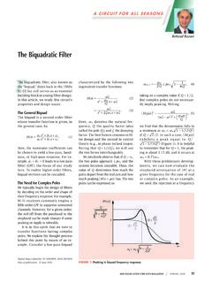
8 14 Changes to Current Consumption Section, Table 5, Table 6, and Table 7 .. 16 Changes to Table 8 .. 17 Change to Table 13 .. 20 Changes to General Section and Observation Receiver Section .. 114 Added Table 14; Renumbered Sequentially .. 114 Added JTAG Boundary Scan Section, Table 15, and Table 16 .. 116 Changes to Data Interface Section, Table 17, Table 18, and Table 19 .. 117 11/2019 Revision 0: Initial Version Data Sheet ADRV9026 Rev. C | Page 3 of 131 FUNCTIONAL BLOCK DIAGRAM 22382-001 SERDOUTA SERDOUTB SYNCOUT1 SYNCOUT2 ORX_CTRL_xRXx_ENGPINT2 GPINT1 TXx_ENRESETTEST_ENSPI_DIOSPI_DOSPI_ENSPI _CLKSYSREF DEVCLK GPIO_xAUXADC_xGPIO_ANA_xJESD204B/JESD204 CSERIALINTERFACERX1+RX1 RX2+RX2 RX3+RX3 RX4+RX4 ADCADCRx1Rx2RX1, RX2, TX1, TX2, ORX1/ORX2RX3, RX4, TX3, TX4, ORX3/ORX40 90 MUXLO1LO2 MUXLO1LO2 MUXLO3 DECIMATION,PROGRAMMABLE FIR,AGC,DC-OFFSET,QEC,TUNING,RSSI,OVERLO ADTX1+TX1 TX2+TX2 TX3+TX3 TX4+TX4 DACDACTx1Tx2pFIR,LO LEAKAGE,QEC,TUNING,INTERPOLATIONORX1+ORX 1 ORX2+ORX2 ORX3+ORX3 ORX4+ORX4 VIFVDIG_1P0 VDDA_1P32 VDDA_1P03 VDDA_1P81 ADCADCORX1/ORX2 DECIMATION,pFIR,DC-OFFSET,QEC,TUNING.
9 OVERLOADPOWERMANAGEMENTCLOCK GENERATIONANDSYNCHRONIZATIONGPIOAUXILIAR Y ADCAUXILIARY DACSPI PORTCONTROLINTERFACERF SYNTHLO3 MICROPROCESSORSERDOUTC SERDOUTD SYNCIN1 SYNCIN2 SYNCIN3 SERDINA SERDINB SERDINC SERDIND 8444419RF SYNTHRF SYNTHLO1LO21 VDDA_1P8 REPRESENTS VCONV1_1P8, VCONV2_1P8,VANA1_1P8,VANA2_1P8,VANA3_1P8 ,VANA4_1P8,AND REPRESENTSVANA1_1P3,VANA2_1P3, VCONV1_1P3, VCONV2_1P3, VRFVCO1_1P3, VRFVCO2_1P3,VAUXVCO_1P3, VCLKVCO_1P3, VRFSYN1_1P3, VRFSYN2_1P3, VCLKSYN_1P3,VAUXSYN_1P3, VRXLO_1P3,AND REPRESENTS VJSYN_1P0, VDES_1P0, VTT_DES,AND 90 0 90 Figure 1. ADRV9026 Data Sheet Rev. C | Page 4 of 131 SPECIFICATIONS Electrical characteristics at ambient temperature range. Power supplies are as follows: VDDA_1P8 = V, VIF = V, VDDA_1P3 = V, VDDA_1P0 = V, and VDIG_1P0 = V. VDDA_1P8 represents VCONV1_1P8, VCONV2_1P8, VANA1_1P8, VANA2_1P8, VANA3_1P8, VANA4_1P8, and VJVCO_1P8. VDDA_1P3 represents VANA1_1P3, VANA2_1P3, VCONV1_1P3, VCONV2_1P3, VRFVCO1_1P3, VRFVCO2_1P3, VAUXVCO_1P3, VCLKVCO_1P3, VRFSYN1_1P3, VRFSYN2_1P3, VCLKSYN_1P3, VAUXSYN_1P3, VRXLO_1P3, and VTXLO_1P3.
10 VDDA_1P0 represents VJSYN_1P0, VDES_1P0, VTT_DES, and VSER_1P0. All RF specifications are based on measurements that include printed circuit board (PCB) and matching circuit losses, unless otherwise noted. Device configuration profile: Receiver = 200 MHz bandwidth, I/Q rate = MHz, transmitter = 200 MHz large signal bandwidth plus 450 MHz synthesis bandwidth, I/Q rate = MHz, Observation receiver (ORX) = 450 MHz bandwidth, I/Q rate = MHz, device clock = MHz, unless otherwise noted. Characterization at 75 MHz followed this profile: Receiver = MHz bandwidth, I/Q rate = MHz, transmitter = MHz large signal bandwidth plus 141 MHz synthesis bandwidth, I/Q rate = MHz, Observation receiver = 141 MHz bandwidth, I/Q rate = MHz, device clock = MHz. Note: if signals are placed outside of the primary bandwidth, degradation in linearity, image rejection, and flatness may be observed. TRANSMITTERS AND RECEIVERS Table 1.