Example: marketing
Lecture 25: CS, CD and CG circuits
start discussing multistage and cascaded circuits, which are in chapter 9 of the text. Department of EECS University of California, Berkeley EECS 105 Spring 2004, Lecture 25 Prof. J. S. Smith Lecture Outline zMOS Common Source Amp zCurrent Source Active Load zCommon Gate Amp zCommon Drain Amp
Tags:
Information
Domain:
Source:
Link to this page:
Documents from same domain
EE105 –Fall 2015 Microelectronic Devices and Circuits
inst.eecs.berkeley.eduSummary of MOS Single-Transistor Amplifiers MOS Common Source Common Source with Deg. Common Drain Common Gate Ri ∞ ∞ ∞ Small Ro Large Very Large Small Large
Diodes and Transistors
inst.eecs.berkeley.eduDiodes and Transistors 1. ... basic semiconductor physics. We won’t discuss the details because the point of this ... switch. Below the specified ...
HSPICE Tutorial - University of California, Berkeley
inst.eecs.berkeley.eduHSPICE Tutorial Contents 1 Introduction 1 ... ee105 spice tutorial example 1 - simple rc circuit in the Results Browser and double-clicking vs and vo to plot them in the graph. You may have been able to guess from the netlist, but you’ll see that vsis a …
Introduction to LabVIEW - University of California, …
inst.eecs.berkeley.eduIntroduction to LabVIEW 1. Introduction Welcome to the LabVIEW component of EE100! This lab is just a simple introduction to the graphical circuit simulation ...
Introduction to LabVIEW For Use in Embedded …
inst.eecs.berkeley.eduUC Berkeley EE249 Hugo.Andrade@ni.com Introduction to LabVIEW For Use in Embedded System Development
Introduction to Digital Systems - University of …
inst.eecs.berkeley.eduDepartment of EECS EE100/42-43 Spring 2007 Rev. 1 Introduction to Digital Systems 0. Acknowledgments Many thanks to Prof. Bernhard Boser and National Instruments for funding this project in the
EE126: Probability and Random Processes - Lecture 1 ...
inst.eecs.berkeley.eduprobability 4 The probabilities summed over all of the base outcomes always equals 1 Example: Toss a fair coin twice 1 Base outcomes are HH,HT,TH,TT 2 This covers all the possibilities. M.E. 3 Each of these outcomes is equally likely 4 Assign each outcome a probability of 0:25. The list (set) of base outcomes is called the Sample Space.
EECS 126 Probability and Random Processes: Course Syllabus ...
inst.eecs.berkeley.eduDescription: Probability is a mathematical discipline that allows one to reason about uncertainty: it helps us to predict uncertain events, to make better decisions under uncertainty, and to design and build systems. Throughout the course, we will teach you the fundamental ideas of probability and random processes along with the labs.
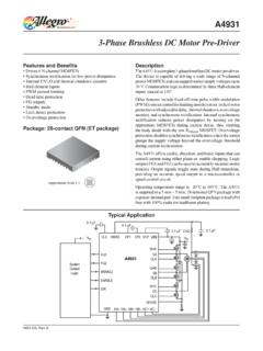
3-Phase Brushless DC Motor Pre-Driver
inst.eecs.berkeley.eduDescription The A4931 is a complete 3-phase brushless DC motor pre-driver . The device is capable of driving a wide range of N-channel power MOSFETs and can support motor supply voltages up to
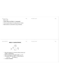
DS -V I G - EECS Instructional Support Group Home Page
inst.eecs.berkeley.eduG D S I D I G-V DS + + V G S _ NMOS I-V CHARACTERISTIC • Since the transistor is a 3-terminal device, there is no single I-V characteristic. • Note that because of the gate insulator, I G = 0 A. • We typically define the MOS I-V characteristic as I D vs. V DS for a fixed V GS. • 3 modes of operation
Related documents

A Single-Supply Op-Amp Circuit Collection
mil.ufl.eduThere have been many excellent collections of op-amp circuits in the past, but all of them focus exclusively on split-supply circuits. Many times, the designer who has to operate a circuit from a single supply does not know how to do the conversion. Single-supply operation requires a little more care than split-supply circuits. The designer should

Chapter 13: Basic Op-Amp Circuits - An-Najah National ...
staff-old.najah.educircuits. The basic circuits for op-amp’s are 1-Comparators 2-Summing Amplifiers 3-Integrators and Differentiators. 13.1: Comparators A comparator is a specialized nonlinear op-amp circuit that compares between two input voltages and produces an output state that indicates which one is greater. Comparators

Op Amps for MEMS Microphone Preamp Circuits
www.analog.comThis application note covers some of the key op amp specifi-cations to consider in a preamp design, show s a few basic circuits, and provides a table of Analog Devices, Inc., op amps that may be appropriate for a preamp design. The . ADMP504 MEMS micro-phone is used as an example in this application note to describe different design choices.
'Single-Supply Op Amp Design Techniques'
www.ti.comFigure 3. Split-Supply Op Amp Circuit With Common-Mode Voltage When signal sources are referenced to ground, single-supply op amp circuits exhibit a large input common-mode voltage. Figure 4 shows a single-supply op amp circuit that has its …
OPERATIONAL AMPLIFIERS: Basic Circuits and Applications
people.engr.tamu.eduEdgar Sanchez-Sinencio, Texas A & M University ELEN 457 Outline of the course •Introduction & Motivation OP Amp Fundamentals •Circuits with Resistive Feedback • Basic Operators: Differential, Integrator, Low Pass •Filters •Static Op Amp Limitations •Dynamic Op Amp Limitations •Noise •Nonlinear Circuits •Signal Generators • Voltage Reference and Linear …

Operational Amplifier Circuits - MIT OpenCourseWare
ocw.mit.eduOperational Amplifier Circuits Review: Ideal Op-amp in an open loop configuration Ro Ri + _ Vp Vn Vi + _ AVi + Vo Ip In An ideal op-amp is characterized with infinite open–loop gain A→∞ The other relevant conditions for an ideal op-amp are: 1. Ip =In =0 2. Ri =∞ 3. Ro =0 Ideal op-amp in a negative feedback configuration

Cascaded Amplifiers -- Two-Stage Op Amp Design
class.ece.iastate.educapacitors with ss open circuits and, one at a time, select C Lh and determine the impedance facing it, say R Lh if all other low-frequency capacitors are replaced with ss open circuits. Then an approximation for the pole corresponding to C Lh is p Lh =-1/(R Lh C Lh) 4. To find the m high-frequency poles, replace all independent voltage sources ...
Solving circuits directly using Laplace
tuttle.merc.iastate.eduEE 230 Laplace circuits – 10 Let’s try an op-amp with a step-voltage input. Find the frequency-domain expression for the output, V o(s). Example 5 – + C R 2 R 1 v o (t) 0 v i (t) V f t = 0 V i (s) = V f s Z R1 = R 1 Z R2 = R 2 Z C = 1 sC Convert to the frequency domain. – + Z R1 Z R2 Z C V i (s) V o (s) First, combine Z R2 and Z C to ...
CIRCUITS LABORATORY EXPERIMENT 9 Operational Amplifiers
classes.engineering.wustl.eduCIRCUITS LABORATORY EXPERIMENT 9 Operational Amplifiers 9.1 INTRODUCTION An operational amplifier ("op amp") is a direct-coupled, differential-input, high- gain voltage amplifier, usually packaged in the form of a small integrated circuit.