Transcription of LT1001 - Precision Operational Amplifier
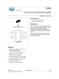
1 1LT10 011001fbTYPICAL APPLICATIOUAPPLICATIO SUDESCRIPTIOUFEATURESP recision OperationalAmplifiernGuaranteed Low Offset VoltageLT1001AM15 V maxLT1001C60 V maxnGuaranteed Low V/ C V/ C maxnGuaranteed Low Bias CurrentLT1001AM2nA maxLT1001C4nA maxnGuaranteed CMRRLT1001AM114dB minLT1001C110dB minnGuaranteed PSRRLT1001AM110dB minLT1001C106dB minnLow Power DissipationLT1001AM75mW maxLT1001C80mW maxnLow Noise VP-PThe LT 1001 significantly advances the state-of-the-art of Precision Operational amplifiers. In the design,processing, and testing of the device, particular atten-tion has been paid to the optimization of the entiredistribution of several key parameters. Consequently,the specifications of the lowest cost, commercial tem-perature device, the LT1001C, have been dramaticallyimproved when compared to equivalent grades of com-peting Precision , the input offset voltage of all units is lessthan 50 V (see distribution plot below).
2 This allows theLT1001AM/883 to be specified at 15 V. Input bias andoffset currents, common-mode and power supply re-jection of the LT1001C offer guaranteed performancewhich were previously attainable only with expensive,selected grades of other devices. Power dissipation isnearly halved compared to the most popular precisionop amps, without adversely affecting noise or speedperformance. A beneficial by-product of lower dissipa-tion is decreased warm-up drift. Output drive capabilityof the LT1001 is also enhanced with voltage gainguaranteed at 10mA of load current. For similar perfor-mance in a dual Precision op amp, with guaranteedmatching specifications, see the LT1002. Shown belowis a platinum resistance thermometer amplifiersnStrain gauge amplifiersnLow level signal processingnHigh accuracy data acquisitionINPUT OFFSET VOLTAGE ( V) 60 NUMBER OF UNITS200150100500201001 TA02 40 2004060954 UNITSFROM THREE RUNST ypical Distributionof Offset VoltageVS = 15V, TA = 25 CLinearized Platinum Resistance Thermometerwith C Accuracy Over 0 to 100 C + LT1001 +LT1001236R plat.
3 1k = 0 C10k* **LM129+15236200 1001 TA01 LINEARITYTRIMGAINTRIMOUTPUT0 TO 10V =0 TO 100 C1 f10k*10k** ULTRONIX 105A WIREWOUND** 1% FILM PLATINUM RTD118MF (ROSEMOUNT, INC.) Trim sequence: trim offset (0 C = ),trim linearity (35 C = ), trim gain(100 C = ). Repeat until all threepoints are fixed with *20kOFFSET TRIM20k330k*1 MEG.**, LTC and LT are registered trademarks of Linear Technology PARAMETERCONDITIONSMINTYPMAXMINTYPMAXUNI TSVOSI nput Offset VoltageNote 2LT1001AM/8837151860 VLT1001AC1025 VOSLong Term Input Offset Voltage TimeStabilityNotes 3 and V/monthIOSI nput Offset Bias Current Noise to 10Hz (Note 3) Vp-penInput Noise Voltage DensityfO = 10Hz (Note 6) HzfO = 1000Hz (Note 3) HzAVOLL arge Signal Voltage GainRL 2k , VO = 12V450800400800V/mVRL 1k VO = 10V300500250500V/mVCMRRC ommon Mode Rejection RatioVCM = 13V114126110126dBPSRRP ower Supply Rejection RatioVS = 3V to 18V110123106123dBRinInput Resistance Differential Mode301001580M ABSOLUTE MAXIMUM RATINGSWWWUS upply Voltage.
4 22 VDifferential Input Voltage .. 30 VInput Voltage .. 22 VOutput Short Circuit Duration .. IndefiniteORDERPART NUMBERLT1001 AMH/883LT1001 MHLT1001 ACHLT1001 CHPACKAGE/ORDER INFORMATIONWUULT1001 ACN8LT1001CN8LT1001CS8S8 PART MARKING1001 ELECTRICAL CHARACTERISTICSTOP VIEWOFFSET ADJUSTV+ INOUTNC ++INV (CASE)87653214H PACKAGE METAL CAN12348765 TOP VIEWV+OUTNC IN+INV +VOSTRIMVOSTRIMS8 PACKAGE8 PIN PLASTIC SON8 PACKAGE8 PIN PLASTIC DIP(Note 1)J8 PACKAGE8 PIN HERMETIC DIPLT1001 AMJ8/883LT1001MJ8LT1001 ACJ8LT1001CJ8 ORDERPART NUMBERORDERPART NUMBEROBSOLETE PACKAGEOBSOLETE PACKAGEC onsult LTC Marketing for parts specified with wider operating temperature l denotes the specifications which apply over the full operatingtemperature range, otherwise specifications are at TA = 25 C. VS = 15V, unless otherwise notedTJMAX = 150 C, JA = 150 C/W, jc = 45 C/WTJMAX = 150 C, JA = 130 C/W (N)TJMAX = 150 C, JA = 150 C/W (S)TJMAX = 150 C, JA = 100 C/W (J)Operating Temperature RangeLT1001AM/LT1001M (OBSOLETE).
5 55 C to 150 CLT1001AC/LT1001C .. 0 C to 125 CStorage: All Devices .. 65 C to 150 CLead Temperature (Soldering, 10 sec.) .. 300 CConsider the N8 and S8 Packages for Alternate SourceConsider the N8 and S8 Packages for Alternate Source3LT10 011001fbELECTRICAL CHARACTERISTICSLT1001AM/883LT1001 MSYMBOL PARAMETERCONDITIONSMINTYPMAXMINTYPMAXUNI TSVOSI nput Offset Voltagel306045160 V VOSA verage Offset Voltage V/ C TempIOSI nput Offset Bias Currentl Signal Voltage GainRL 2k , VO = 10Vl300700200700V/mVCMRRC ommon Mode Rejection RatioVCM = 13Vl110122106120dBPSRRP ower Supply Rejection RatioVS = 3 to 18Vl104117100117dBInput Voltage Rangel 13 14 13 14 VVOUTO utput Voltage SwingRL 2k l DissipationNo loadl559060100mWVS = 15V, 55 C TA 125 C, unless otherwise notedLT1001 ACLT1001 CSYMBOL PARAMETERCONDITIONSMINTYPMAXMINTYPMAXUNI TSVOSI nput Offset Voltagel206030110 V VOSA verage Offset Voltage V/ C TempIOSI nput Offset Bias Currentl Signal Voltage GainRL 2k.
6 VO = 10Vl350750250750V/mVCMRRC ommon Mode Rejection RatioVCM = 13Vl110124106123dBPSRRP ower Supply Rejection RatioVS = 3V to 18Vl106120103120dBInput Voltage Rangel 13 14 13 14 VVOUTO utput Voltage SwingRL 2k l DissipationNo loadl5085 5590mWNote 1: Absolute Maximum Ratings are those values beyond which the lifeof a device may be 2: Offset voltage for the LT1001AM/883 and LT1001AC are measuredafter power is applied and the device is fully warmed up. All other gradesare measured with high speed test equipment, approximately 1 secondafter power is applied. The LT1001AM/883 receives 168 hr. burn-in at125 C. or 3: This parameter is tested on a sample basis 4: Long Term Input Offset Voltage Stability refers to the averagedtrend line of VOS versus Time over extended periods after the first 30 daysof operation. Excluding the initial hour of operation, changes in VOS duringthe first 30 days are typically 5: Parameter is guaranteed by 6: 10Hz noise voltage density is sample tested on every lot.
7 Devices100% tested at 10Hz are available on = 15V, 0 C TA 70 C, unless otherwise notedLT1001AM/883LT1001 ACLT1001M/ LT1001 CSYMBOL PARAMETERCONDITIONSMINTYPMAXMINTYPMAXUNI TSI nput Voltage Range 13 14 13 14 VVOUTM aximum Output Voltage SwingRL 2k 13 14 13 14 VRL 1k 12 12 RateRL 2k (Note 5) sGBWGain-Bandwidth Product(Note 5) DissipationNo load 46 75 48 80mWNo load, VS = 3V 4 6 4 8mWThe l denotes the specifications which apply over the full operatingtemperature range, otherwise specifications are at TA = 25 C. VS = 15V, TA = 25 C, unless otherwise noted4LT10011001fbTYPICAL PERFORMANCE CHARACTERISTICS UWTIME AFTER POWER ON (MINUTES)0 CHANGE IN OFFSET VOLTAGE ( V)432141001 G031235VS = 15 VTA = 25 CMETAL CAN (H) PACKAGEDUAL-IN-LINE PACKAGEPLASTIC (N) OR CERDIP (J)Long Term Stability of FourRepresentative to 10Hz NoiseTIME (SECONDS)0 NOISE VOLTAGE 100nV/DIV81001 G0424610 TEMPERATURE ( C) G07 25050100125 INPUT BIAS AND OFFSET CURRENTS (nA)VS = 15 VBIAS CURRENTOFFSET CURRENTI nput Bias and Offset Currentvs Temperature DIFFERENTIAL INPUT (V) OR NON-INVERTINGINPUT BIAS CURRENT (mA) G09VS = 15 VTA = 25 CIB 1 nA to VDIFF = (MONTHS)0 OFFSET VOLTAGE CHANGE ( V)41001 G0612351050 5 10 COMMON MODE INPUT VOLTAGE 15 INPUT BIAS CURRENT (nA).
8 5 10 5051001 G081015VS = 15 VTA = 25 CDEVICE WITH POSITIVE INPUT CURRENTDEVICE WITH NEGATIVE INPUT CURRENT +VCMIbCOMMON MODEINPUT RESISTANCE = = 280G (Hz) G05 VOLTAGE NOISE nV/ HzTA = 25 CVS = 3 TO 18 VVOLTAGECURRENT1/f CORNER70Hz1/f NOISE pA/ HzNoise SpectrumOFFSET VOLTAGE DRIFT ( V/ C) OF UNITS10080604020+ G01 + + UNITSTESTEDI nput Bias CurrentOver the Common Mode RangeInput Bias Current vsDifferential Input VoltageTEMPERATURE ( C) 50 OFFSET VOLTAGE ( V)50403020100 10 20 30 40 50050751001 G02 2525100125LT1001LT1001 ALT1001 ALT1001VS = 15 VWarm-Up DriftOffset Voltage Drift withTemperatureof Representative UnitsTypical Distribution of OffsetVoltage Drift with Temperature5LT10 011001fbTYPICAL PERFORMANCE CHARACTERISTICS UWCommon Mode Limitvs TemperatureTEMPERATURE C 50V+ + + + + + 25751001 G13 25050100125 COMMON MODE LIMIT (V)REFERRED TO POWER SUPPLYV = to 4V V = 12 to 18V V+ = 12 to 18V V+ = to 4V FREQUENCY (MHz) GAIN (dB)PHASE SHIFT (DEG)11001 G12 PHASE MARGIN 55 C = 63 125 C = 57 201612840 4 8801001201401601802002202 PHASE 25 CGAIN 125 CVS = 15 VGAIN 25 C & 55 C25 CPHASEMARGIN= 60 Gain, Phase Shift vs FrequencyFREQUENCY (Hz) LOOP VOLTAGE GAIN (dB)10M1001 G111010010k1M11k100k140120100806040200 20TA = 25 CVS = 15 VVS = 3 VOpen Loop Voltage GainFrequency ResponseFREQUENCY (Hz)1 COMMON MODE REJECTION (dB)14012010080604020101001k10k1001 G14100k1 MVS = 15 VTA = 25 CCommon Mode Rejection Ratiovs FrequencySUPPLY VOLTAGE (V)SUPPLY CURRENT (mA) 9 151001 G16 3 6 12 18 21 55 C125 C25 CSupply Current vs Supply VoltageLOAD RESISTANCE ( ) 100300 OUTPUT SWING (V)161284010003k10k1001 G17VS = 15 VTA = 25 CPOSITIVE SWINGNEGATIVE SWINGO utput Swing vs Load ResistanceTEMPERATURE ( C)
9 501200k1000k800k600k400k200k025751001 G10 25050100125 OPEN LOOP VOLTAGE GAIN (V/V)VS = 15V, VO = 12 VVS = 3V, VO = 1 VOpen Loop Voltage Gainvs TemperatureTIME FROM OPUTPUT SHORT (MINUTES)0 SHORT CIRCUIT CURRENT (mA)SINKING 25040302010 10 20 30 40 501001 G18134 55 C 55 C25 C25 C125 C125 CVS = 15 VSOURCINGO utput Short-Circuit Currentvs TimeFREQUENCY (Hz)POWER SUPPLY REJECTION (dB)1401201008060402001001 = 15V 1V p-pTA = 25 CNEGATIVE SUPPLYPOSITIVE SUPPLYP ower Supply Rejection Ratiovs Frequency6LT10011001fbTYPICAL PERFORMANCE CHARACTERISTICS UWVoltage Follower Overshootvs Capacitive LoadSmall Signal Transient Response1001 G22AV = +1, CL = 50pF1001 G19 Large Signal Transient ResponseFREQUENCY (kHz)1 OUTPUT VOLTAGE, PEAK-TO-PEAK (V)28242016128401010010001001 G23VS = 15 VTA = 25 CMaximum UndistortedOutput vs. FrequencyFREQUENCY (Hz)1 OUTPUT IMPEDANCE ( ) G24101001k100kAV = 1000AV = +1IO = 1mAVS = 15 VTA = 25 CClosed Loop Output ImpedanceAV = +1, CL = 1000pF1001 G21 Small Signal Transient ResponseCAPACITIVE LOAD (pF)100 PERCENT OVERSHOOT1001 G20100010,000100,000100806040200VS = 15 VTA = 25 CVIN = 100mVRL > 50kApplication Notes and Test CircuitsThe LT1001 series units may be inserted directly intoOP-07, OP-05, 725, 108A or 101A sockets with or withoutremoval of external frequency compensation or nullingcomponents.
10 The LT1001 can also be used in 741, LF156or OP-15 applications provided that the nulling circuitry LT1001 is specified over a wide range of power supplyvoltages from 3V to 18V. Operation with lower suppliesis possible down to (two Ni-Cad batteries). How-ever, with supplies, the device is stable only inclosed loop gains of + 2 or higher (or inverting gain of oneor higher).APPLICATIONS INFORMATIONWUUUU nless proper care is exercised, thermocouple effectscaused by temperature gradients across dissimilar metalsat the contacts to the input terminals, can exceed theinherent drift of the Amplifier . Air currents over deviceleads should be minimized, package leads should beshort, and the two input leads should be as close togetheras possible and maintained at the same Circuit for Offset Voltage and its Drift with Temperature + 15 VLT1001+15V*50k*100 *50k2376VO1001 F01VO = 1000 VOS* RESISTORS MUST HAVE LOWTHERMOELECTRIC POTENTIAL.