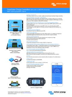
Transcription of LT3652 - Power Tracking 2A Battery Charger for Solar Power
1 LT365213652feFor more information APPLICATIONDESCRIPTIONP ower Tracking 2A Battery Charger for Solar PowerThe LT 3652 is a complete monolithic step-down bat-tery Charger that operates over a to 32V input voltage range. The LT3652 provides a constant-current/constant-voltage charge characteristic, with maximum charge current externally programmable up to 2A. The Charger employs a float voltage feedback reference, so any desired Battery float voltage up to can be programmed with a resistor LT3652 employs an input voltage regulation loop, which reduces charge current if the input voltage falls below a programmed level, set with a resistor divider. When the LT3652 is powered by a Solar panel, the input regulation loop is used to maintain the panel at peak output LT3652 can be configured to terminate charging when charge current falls below 1/10 of the programmed maximum (C/10).
2 Once charging is terminated, the LT3652 enters a low-current (85 A) standby mode. An auto-re-charge feature starts a new charging cycle if the Battery voltage falls below the programmed float voltage. The LT3652 also contains a programmable safety timer, used to terminate charging after a desired time is reached. This allows top-off charging at currents less than C/10. 2A Solar Panel Power Manager With LiFePO4 Battery and 17V Peak Power TrackingFEATURESAPPLICATIONSn Input Supply Voltage Regulation Loop for Peak Power Tracking in (MPPT) Solar Applicationsn Wide Input Voltage Range: to 32V (40V Abs Max)n Programmable Charge Rate Up to 2An User Selectable Termination: C/10 or On-Board Termination Timern Resistor Programmable Float Voltage Up to Accommodates Li-Ion/Polymer, LiFePO4, SLA Chemistriesn No VIN Blocking Diode Required for Battery Voltages 1 MHz Fixed Frequencyn Float Voltage Reference Accuracyn 5% Charge Current Accuracyn C/10 Detection Accuracyn Binary-Coded Open-Collector Status Pinsn Thermally Enhanced 12-Lead 3mm 3mm DFN and MSE Packagesn Solar Powered Applicationsn Remote Monitoring Stations n LiFePO4 (Lithium Phosphate) Applicationsn Portable Handheld Instruments n 12V to 24V Automotive SystemsSolar Panel Input Voltage Regulation, Tracks Max Power Point to Greater Than 98%SWVINSOLAR PANEL INPUT(<40V OC VOLTAGE)VIN_REGVFBBOOSTSENSEBATNTCTIMERC MSH3-40 MASYSTEM LOAD1 F542k459k3652 TA01a10kB = 33802-CELL LiFePO4 (2 )
3 Battery PACK+10 FCMSH1-40MA10 F10 OUTPUT CURRENT (A) REGULATION VOLTAGE (V) TO 98% PEAK POWER98% TO 95% PEAK POWERTA = 25 CL, LT, LTC, LTM, Linear Technology and the Linear logo are registered trademarks and PowerPath is a trademark of Linear Technology Corporation. All other trademarks are the property of their respective owners. LT365223652feFor more information CONFIGURATIONABSOLUTE MAXIMUM RATINGSV oltages: VIN ..40V VIN_REG, SHDN, CHRG, FAULT ..VIN + , 40V SW ..40V BOOST ..SW+10V, 50V BAT, SENSE ..15V(Note 1)ORDER INFORMATIONLEAD FREE FINISHTAPE AND REELPART MARKING*PACKAGE DESCRIPTIONTEMPERATURE RANGELT3652 EDD#PBFLT3652 EDD#TRPBFLFHT12-Lead Plastic DFN 3mm 3mm 40 C to 125 CLT3652 IDD#PBFLT3652 IDD#TRPBFLFHT12-Lead Plastic DFN 3mm 3mm 40 C to 125 CLT3652 EMSE#PBFLT3652 EMSE#TRPBF365212-Lead Plastic MSOP 40 C to 125 CLT3652 IMSE#PBFLT3652 IMSE#TRPBF365212-Lead Plastic MSOP 40 C to 125 CConsult LTC Marketing for parts specified with wider operating temperature more information on lead free part marking, go to: For more information on tape and reel specifications, go to.
4 Some packages are available in 500 unit reels through designated sales channels with #TRMPBF VIEWDD PACKAGE12-LEAD (3mm 3mm) PLASTIC DFN1211891045321 SWBOOSTSENSEBATNTCVFBVINVIN_REGSHDNCHRGF AULTTIMER6713 GND123456 VINVIN_REGSHDNCHRGFAULTTIMER121110987 SWBOOSTSENSEBATNTCVFBTOP VIEW13 GNDMSE PACKAGE12-LEAD PLASTIC MSOPTJMAX = 125 C, JA = 43 C/W, JC = 3 C/W EXPOSED PAD (PIN 13) IS GND, MUST BE SOLDERED TO PCBTJMAX = 125 C, JA = 43 C/W, JC = 3 C/W EXPOSED PAD (PIN 13) IS GND, MUST BE SOLDERED TO PCB BAT-SENSE .. to + NTC, TIMER, .. VFB ..5 VOperating Junction Temperature Range (Note 2) .. 40 C to 125 CStorage Temperature Range .. 65 C to 150 CLT365233652feFor more information Operating Range VIN Start VoltageVBAT = (Notes 3, 4) VBAT = (Note 4)l VVIN(OVLO)OVLO Threshold OVLO HysteresisVIN Risingl3235 140V VVIN(UVLO)UVLO Threshold UVLO HysteresisVIN VVFB(FLT)Float Voltage Reference(Note 6) V VRECHARGER echarge Reference ThresholdVoltage Relative to VFB(FLT) (Note 6) (PRE)Reference Precondition ThresholdVFB Rising (Note 6) (PREHYST)Reference Precondition Threshold HysteresisVoltage Relative to VFB(PRE) (Note 6)70mVVIN_REG(TH)Input Regulation ReferenceVFB = 3V.
5 VSENSE VBAT = Regulation Reference Bias CurrentVIN_REG = VIN_REG(TH)l35100nAIVINO perating Input Supply CurrentCC/CV Mode, ISW = 0 Standby Mode Shutdown (SHDN = 0) 85 A AIBOOSTBOOST Supply CurrentSwitch On, ISW = 0, < V(BOOST SW) < Switch DriveISW = 2A30mA/AVSW(ON)Switch-On Voltage DropVIN VSW, ISW = 2A350mVISW(MAX)Switch Current (PRE)Precondition Sense VoltageVSENSE VBAT; VFB = 2V15mVVSENSE(DC)Maximum Sense VoltageVSENSE VBAT; VFB = 3V (Note 7)l95100105mVVSENSE(C/10)C/10 Trigger Sense VoltageVSENSE VBAT, Input Bias CurrentCharging AISENSESENSE Input Bias CurrentCharging AIREVERSEC harger Reverse Current IBAT + ISENSE + ISWVIN = 0; VBAT = VSENSE = VSW = AIVFBVFB Input Bias CurrentCharging Terminated65nAIVFBVFB Input Bias CurrentCV Operation (Note 5)110nAVNTC(H)NTC Range Limit (High)VNTC (L)NTC Range Limit (Low)VNTC (HYST)NTC Threshold Hysteresis% of threshold20%RNTC(DIS)NTC Disable ImpedanceImpedance to groundl250500k INTCNTC Bias CurrentVNTC = AVSHDNS hutdown (HYST)Shutdown Hysteresis120mVISHDNSHDN Input Bias Current 10nAVCHRG, VFAULTS tatus Low Voltage10mA Current25 AVTIMER(DIS)Timer Disable The l denotes the specifications which apply over the full operating temperature range, otherwise specifications are at TA = 25 C (Note 2).
6 VIN = 20V, Boost SW = 4V, SHDN = 2V, VFB = , CTIMER = 0 .6 8 CHARACTERISTICSLT365243652feFor more information Charge Cycle Timeout3hrPrecondition Accuracyl 1010%fOOperating Frequency1 MHzDCDuty Cycle RangeContinuous Operationl1590% The l denotes the specifications which apply over the full operating temperature range, otherwise specifications are at TA = 25 C (Note 2). VIN = 20V, Boost SW = 4V, SHDN = 2V, VFB = , CTIMER = 0 .6 8 1: Stresses beyond those listed under Absolute Maximum Ratings may cause permanent damage to the device. Exposure to any Absolute Maximum Rating condition for extended periods may affect device reliability and 2: The LT3652 EDD is guaranteed to meet performance specifications from 0 C to 125 C junction temperature.
7 Specifications over the 40 C to 125 C operating junction temperature range are assured by design, characterization, and correlation with statistical process controls. The LT3652 IDD specifications are guaranteed over the full 40 C to 125 C operating junction temperature range. Note that the maximum ambient temperature consistent with these specifications is determined by specific operating conditions in conjunction with board layout, the rated package thermal impedance and other environmental 3: VIN minimum voltages below the start threshold are only supported if (VBOOST-VSW) > 4: This parameter is valid for programmed output Battery float voltages VIN operating range minimum is above the programmed output Battery float voltage (VBAT(FLT) + ). VIN Start Voltage is above the programmed output Battery float voltage (VBAT(FLT) + ).
8 Note 5: Output Battery float voltage (VBAT(FLT)) programming resistor divider equivalent resistance = 250k compensates for input bias current. Note 6: All VFB voltages measured through 250k series 7: VSENSE(DC) is reduced by thermal foldback as junction temperature approaches 125 CHARACTERISTICSLT365253652feFor more information PERFORMANCE CHARACTERISTICSS witch Forward Drop (VIN VSW) vs TemperatureCC/CV Charging; SENSE Pin Bias Current vs VSENSEC/10 Threshold (VSENSE VBAT) vs TemperatureVFB Reference Voltage vs TemperatureVIN Standby Mode Current vs TemperatureSwitch Drive (ISW/IBOOST) vs Switch CurrentTJ = 25 C, unless otherwise ( C) 50 VFB (FLT) 2525100125 TEMPERATURE ( C) 5065 IVIN CURRENT ( A)70758010090050753652 G029585 2525100 SWITCH CURRENT (A)0 ISW/IBOOST G03 TEMPERATURE ( C) 50320 VSW(ON) (mV)340360380480420050753652 G04440460400 2525100125 ISW = 2 AVSENSE (V)0 350 ISENSE ( A) 250 150 300 200 G05 VBAT = VBAT(PRE)VBAT = VBAT(FLT)TEMPERATURE ( C) 508 VSENSE(C/10) (mV)9101112050753652 G06 2525100125 TEMPERATURE ( C) 50 VIN_REG(TH) (V) 2525100125 VIN_REG Threshold vs Temperature.
9 ICHG at 50%LT365263652feFor more information PERFORMANCE CHARACTERISTICSM aximum Charge Current (VSENSE VBAT) vs TemperatureThermal Foldback Maximum Charge Current (VSENSE VBAT) vs Temperature CC/CV Charging; BAT Pin Bias Current vs VBATB attery Bias Current with Charger Disabled (IBAT + ISENSE + IBOOST + ISW)TA = 25 C, unless otherwise ( C) (DC) (mV) 2525100125 VFB = 3 VTEMPERATURE ( C)0 VSENSE(DC) (mV)408020601001204565851051253513525557 5951153652 G08 VBAT (V)0 (mA) G10 VBAT(FLT)VIN_REG (V) (DC) (mV) (FLT) (V)020 IRFB ( A)861012163652 G1142648101214 TIME (MINUTES)0 EFFICIENCY (%)CHARGE CURRENT (A); Power LOSS (W) = 20 VMaximum Charge Current (VSENSE VBAT) vs VIN_REG VoltageVFLOAT Programming Resistor Current vs VFLOAT for 2-Resistor NetworkCharge Current, Efficiency, and Power Loss vs Time (ICHG(MAX) = 2A; VFLOAT = ) Charger Efficiency vs Battery Voltage (ICHG = 2A)VBAT (V)70 EFFICIENCY (%)7680828486887472789057911134141536810 123652 G13 VIN = 20V WITH INPUT BLOCKING DIODEVBAT (V)0 Battery CURRENT ( A)0642121410848103652 G111626141216 VIN FLOATINGVIN = 20V; VSHDN = 0 VLT365273652feFor more information FUNCTIONSVIN (Pin 1): Charger Input Supply.
10 VIN operating range is to 32V. VIN must be greater than the pro-grammed output Battery float voltage (VBAT(FLT )) for reli-able start-up. (VIN VBAT(FLT )) is the minimum operating voltage, provided (VBOOST VSW) 2V. IVIN ~ 85 A after charge (Pin 2): Input Voltage Regulation Reference. Maximum charge current is reduced when this pin is below Connecting a resistor divider from VIN to this pin enables programming of minimum operational VIN voltage. This is typically used to program the peak Power voltage for a Solar panel. The LT3652 servos the maximum charge current required to maintain the programmed operational VIN voltage, through maintaining the voltage on VIN_REG at or above If the voltage regulation feature is not used, connect the pin to (Pin 3): Precision Threshold Shutdown Pin.


