Transcription of LT4276 – LTPoE++/PoE+/PoE PD Forward/Flyback …
1 LT427614276faFor more information applicaTion FeaTuresDescripTionLTPoE++/PoE+/PoE PD Forward/Flyback ControllerThe LT 4276 is a pin-for-pin compatible family of IEEE and LTPoE++ Powered Device (PD) controllers. It includes an isolated switching regulator controller capable of synchronous operation in both forward and flyback topologies with auxiliary power LT4276A employs the LTPoE++ classification scheme, receiving , , 70W or 90W of power at the PD RJ45 connector, and is backwards compatible with IEEE The LT4276B is a fully compliant, Type 2 (PoE+) PD.
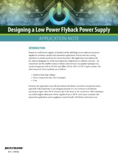
2 The LT4276C is a fully compli-ant, 13W Type 1 (PoE) LT4276 supports both forward and flyback power supply topologies, configurable for a wide range of PoE applications. The flyback topology supports No-Opto feedback. Auxiliary input voltage can be accurately sensed with just a resistor divider connected to the AUX LT4276 utilizes an external, low RDS(ON) N-channel MOSFET for the Hot Swap function, maximizing power delivery and efficiency, reducing heat dissipation, and easing the thermal ++ 70W Power Supply in a Forward ModeapplicaTionsn and LTPoE++ 90W Powered Device (PD) with Forward/Flyback Controllern LT4276A Supports All of the Following Standards.
3 NLTPoE++ , , 70W and 90W nIEEE Compliant nIEEE up to 13W Compliantn LT4276B is IEEE Compliantn LT4276C is IEEE Compliantn Superior Surge Protection (100V Absolute Maximum)n Wide Junction Temperature Range ( 40 C to 125 C)n Auxiliary Power Support as Low as 9Vn No Opto-Isolator Required for flyback Operationn External Hot Swap N-Channel MOSFET for Lowest Power Dissipation and Highest System Efficiencyn >94% End-to-End Efficiency with LT4321 Ideal Bridgen Available in a 28-Lead 4mm 5mm QFN Packagen High Power Wireless Data Systemsn Outdoor Security Camera Equipmentn Commercial and Public Information Displaysn High Temperature ApplicationsL, LT, LTC, LTM, LTPoE++.
4 Linear Technology and the Linear logo are registered trademarks of Linear Technology Corporation. All other trademarks are the property of their respective FamilyMAX DELIVERED POWERLT4276 GRADEABCLTPoE++ 90 WlLTPoE++ 70 WlLTPoE++ ++ l13Wl l l VPORTVPORTRCLASSAUXRCLASS++ F10 FBAV19WS(TRR 50ns)22 FHSGATEHSSRCFFSD LYPGSGITHBTO MICROPROCESSORISEN+ISEN 4276 TA01 GND FB31 ROSCT2 PSS100 HAUX37V-57V+ +FMMT72320m 5V13A+ F100pF10nF100kLT4276 AOPTO+LT427624276faFor more information conFiguraTionabsoluTe MaxiMuM raTingsVPORT, HSSRC, VIN Voltages.
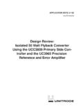
5 To 100 VHSGATE 20mAVCC Voltage .. to 8 VRCLASS, RCLASS++Voltages .. to 8V (and VPORT)SFST, FFSDLY, ITHB, T2P Voltages .. to VCC+ +, ISEN Voltages .. Voltage ..+12V/ 30 VRCLASS/RCLASS++ Current .. 50mAAUX Current .. Current .. 100 ARLDCMP Current .. 500 AT2P Current .. Junction Temperature Range (Note 3) LT4276 AI/LT4276BI/LT4276CI .. 40 C to 85 C LT4276 AH/LT4276BH/LT4276CH .. 40 C to 125 CStorage Temperature Range .. 65 C to 150 C(Notes 1, 2)910 TOP VIEWUFD PACKAGE28-LEAD (4mm 5mm) PLASTIC QFN11121328 27 26 25 241423654321 GNDAUXRCLASS++/NC*RCLASST2P/NC**VCCVCCVC CDNCVCCPGGNDSGISEN+ISEN RLDCMPVPORTNCHSGATEHSSRCVINSWVCCVCCROSCS FSTFFSDLYITHBFB3171718192021221681529 GND TJMAX = 150 C, JC = C/W EXPOSED PAD (PIN 29)
6 IS GND, MUST BE SOLDERED TO PCB*RCLASS++ is not connected in the LT4276B and LT4276C**T2P is not connected in the LT4276C orDer inForMaTionLEAD FREE FINISHTAPE AND REELPART MARKING* MAX PD POWER PACKAGE DESCRIPTIONTEMPERATURE RANGELT4276 AIUFD#PBFLT4276 AIUFD#TRPBF4276A90W28-Lead (4mm 5mm) Plastic QFN 40 C to 85 CLT4276 AHUFD#PBFLT4276 AHUFD#TRPBF4276A90W28-Lead (4mm 5mm) Plastic QFN 40 C to 125 CLT4276 BIUFD#PBFLT4276 BIUFD# (4mm 5mm) Plastic QFN 40 C to 85 CLT4276 BHUFD#PBFLT4276 BHUFD# (4mm 5mm) Plastic QFN 40 C to 125 CLT4276 CIUFD#PBFLT4276 CIUFD#TRPBF4276C13W28-Lead (4mm 5mm) Plastic QFN 40 C to 85 CLT4276 CHUFD#PBFLT4276 CHUFD#TRPBF4276C13W28-Lead (4mm 5mm) Plastic QFN 40 C to 125 CConsult LTC Marketing for parts specified with wider operating temperature ranges.
7 *The temperature grade is identified by a label on the shipping more information on lead free part marking, go to: For more information on tape and reel specifications, go to: Some packages are available in 500 unit reels through designated sales channels with #TRMPBF more information characTerisTicsSYMBOLPARAMETERCONDITIONS MINTYPMAXUNITSVPORT, HSSRC, VIN Operating Voltage At VPORT Pinl60 VVSIGVPORT Signature RangeAt VPORT Classification RangeAt VPORT Mark RangeAt VPORT Pin, After 1st Classification AUX RangeAt VPORT Pin, VAUX Hysteresis Swap Turn-On Voltagel 3537 VVHSOFFHot Swap Turn-Off Voltagel 3031 VHot Swap On/Off Hysteresis Windowl3 VSupply CurrentVPORT.
8 HSSRC & VIN Supply Current VVPORT = VHSSRC = VVIN = 60Vl2mAVPORT Supply Current During Classification VVPORT = , RCLASS, RCLASS++ Supply Current During Mark EventVVPORT = VMARK after 1st Classification and ClassificationSignature ResistanceVSIG (Note 4) Signature Resistance During Mark EventVMARK (Note 4) RCLASS/RCLASS++ Voltage 10mA IRCLASS Stability TimeVVPORT Step to , RCLS = l2msDigital InterfaceVAUXTAUX ThresholdVPORT = , VIN = VHSSRC = Pin CurrentVAUX = , VPORT = , VIN = 9V, VCC = AT2P Output HighVVCC - VT2P, 1mA LeakageVT2P = 0Vl 11 AHot Swap ControlIGPUHSGATE Pull Up CurrentVHSGATE - VHSSRC = 5V (Note 5)
9 L 27 22 18 AHSGATE Voltage 10 A Load, with respect to HSSRCl1014 VHSGATE Pull Down CurrentVHSGATE - VHSSRC = 5Vl400 AVCC SupplyVCCREGVCC Regulation AmplifierVFBFB31 Regulation Pin Bias CurrentRLDCMP A gmFeedback Amplifier Average Trans-ConductanceTime Average, 2 A < IITHB < 2 Al 52 40 26 A/VISINKITHB Average Sink CurrentTime Average, VFB31 = ASoft-StartISFSTC harging CurrentVSFST = , 49 42 36 A The l denotes the specifications which apply over the full operating temperature range, otherwise specifications are at TJ = 25 C.
10 VVPORT = VHSSRC = VVIN = 40V, VVCC = VCCREG, ROSC, PG, and SG Open, RFFSDLY = to GND. AUX connected to GND unless otherwise specified. (Note 2)LT427644276faFor more information OutputsPG, SG Output High LevelI = 1mAlVCC , SG Output Low LevelI = 1mAl1 VPG Rise Time, Fall TimePG = 1000pF15nsSG Rise Time, Fall TimeSG = 400pF15nsCurrent Sense/OvercurrentVFAULTO vercurrent Fault ThresholdVISEN+ - VISEN l125140155mV VSENSE/ VITHBC urrent Sense Comparator Threshold with Respect to VITHBl 130 111 98mV/VVITHB(OS)VITHB Switching FrequencyROSC Pin Openl 200214223kHzSwitching FrequencyROSC = to GNDl280300320kHzfT2 PLTPoE++ Signal FrequencyfSW/256tMINM inimum PG On Timel175250330nsDMAXM aximum PG Duty Cyclel636670%tPGDELAYPG Turn-On Delay- flyback PG Turn-On from FFSDLY to GND from FFSDLY to GND from FFSDLY to VCC from FFSDLY to VCC45 171 92 391ns ns ns nstFBDLYF eedback Amp Enable Delay Time350nstFBFeedback Amp Sense Interval550nstPGSGPG Falling to SG Rising Delay Time- flyback PG Falling to SG Falling Delay Time.