Transcription of LT8334 (Rev. 0)
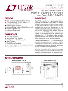
1 LT83341 Rev. AFor more information FeedbackTYPICAL APPLICATION FEATURESDESCRIPTIONLow IQ Boost/SEPIC/Inverting Converter with 5A, 40V SwitchThe LT 8334 is a current mode DC/DC converter with a 40V, 5A switch operating from a to 40V input. With a unique single feedback pin architecture, it is capable of boost, SEPIC or inverting configurations. Burst Mode operation consumes as low as 9 A quiescent current to maintain high efficiency at very low output currents, while keeping typical output ripple below external compensation pin allows optimization of loop bandwidth over a wide range of input and output volt-ages and programmable switching frequencies between 300kHz and 2 MHz. A SYNC/MODE pin allows synchroni-zation to an external clock. It can also be used to select between BURST or PULSE SKIP modes of operation with spread spectrum frequency modulation for low EMI.
2 For increased efficiency, a BIAS pin can accept a second input to supply the INTVCC regulator. Additional features include frequency foldback and programmable soft-start to con-trol inductor current during LT8334 is available in a thermally enhanced 12-lead 4mm 3mm DFN nWide Input Voltage Range: to 40V nUltralow Quiescent Current and Low Ripple Burst Mode Operation: IQ = 9 A n5A, 40V Power Switch nPositive or Negative Output Voltage Programming with a Single Feedback Pin nProgrammable Frequency (300kHz to 2 MHz) nSychronizable to an External Clock nSpread Spectrum Frequency Modulation for Low EMI nBias Pin for Higher Efficiency nProgrammable Undervoltage Lockout (UVLO) nOvercurrent and Overtemperature Protection nThermally Enhanced 12-Lead 4mm 3mm DFN nIndustrial and Automotive nTelecom nMedical Diagnostic Equipment nPortable ElectronicsAll registered trademarks and trademarks are the property of their respective owners.
3 Efficiency and Power F10 F F1nF1 HVIN4V TO 20 VVOUT24V820mA AT VIN = 5V2A AT VIN = AT VIN = 16 VRTSSGNDSYNC/MODEVCLT8334EN/UVLOINTVCCBI ASFBXVINSW8334 TA01aEFFICIENCYPOWER LOSSVIN = 5 VVIN = 12 VLOAD CURRENT (A) (%)POWER LOSS (W)8334 TA01bLT83342 Rev. AFor more information CONFIGURATIONABSOLUTE MAXIMUM RATINGSSW ..40 VVIN, EN/UVLO ..40 VBIAS ..40 VSYNC ..6 VINTVCC ..(Note 2)VC..4 VFBX .. 4 VOperating Junction Temperature Range (Notes 3) LT8 33 4R .. 40 C to 150 CStorage Temperature Range .. 65 C to 150 CMaximum Junction Temperature ..+150 C(Note 1)12111098713 GND123456SW1SW2 SYNC/MODESSRTFBXNCEN/UVLOVININTVCCBIASVC TOP VIEWDE PACKAGE12-LEAD (4mm 3mm) PLASTIC DFN JA = 43 C/W, JC = C/WEXPOSED PAD (PIN 13) IS PGND AND GND, MUST BE SOLDERED TO PCBORDER INFORMATIONLEAD FREE FINISHTAPE AND REELPART MARKING*PACKAGE DESCRIPTIONTEMPERATURE RANGELT8334 RDE#PBFLT8334 RDE#TRPBF833412-Lead (4mm 3mm) Plastic DFN 40 C to 150 CContact the factory for parts specified with wider operating temperature ranges.
4 *The temperature grade is identified by a label on the shipping and reel specifications. Some packages are available in 500 unit reels through designated sales channels with #TRMPBF CHARACTERISTICS The l denotes the specifications which apply over the full operating temperature range, otherwise specifications are at TA = 25 C. VIN = 12V, EN/UVLO = 12V unless otherwise Operating Voltage Quiescent Current at ShutdownVEN/UVLO = l1 12 15 A AVEN/UVLO = l2 25 25 A AVIN Quiescent CurrentSleep Mode (Not Switching)SYNC = 0V l9 915 30 A AActive Mode (Not Switching)SYNC = 0V or INTVCC, BIAS = 0V l1200 12001600 1850 A ASYNC = 0V or INTVCC, BIAS = 5V l22 2240 65 A ABIAS ThresholdRising, BIAS Can Supply INTVCC Falling, BIAS Cannot Supply INTVCC V VIN Falling Threshold to Supply INTVCCBIAS = 12 VBIAS 2 VVBIAS Falling Threshold to Supply INTVCCVIN = 12 VVINVFBX RegulationFBX Regulation VoltageFBX > 0V FBX < 0Vl VFBX Line RegulationFBX > 0V, < VIN < 40V FBX < 0V, < VIN < %/VFBX Pin CurrentFBX = , 1010nALT83343 Rev.
5 AFor more information CHARACTERISTICS The l denotes the specifications which apply over the full operating temperature range, otherwise specifications are at TA = 25 C. VIN = 12V, EN/UVLO = 12V unless otherwise Frequency (fOSC)RT = 165k RT = RT = 20kl l l265 1 2327 MHz MHzSSFM Maximum Frequency Deviation( f/fOSC) 100, RT = 20k142028%Minimum On-TimeBURST Mode, VIN = 12V (Note 6) PULSE SKIP Mode, VIN = 12V (Note 6)70 6090 85ns nsMinimum Off-Timel5075nsSYNC/Mode, Mode Thresholds (Note 5)High (Rising) Low (Falling)l l VSYNC/Mode, Clock Thresholds (Note 5)Rising Fallingl l VfSYNC/fOSC Allowed RatioRT = Pin Current SYNC = 2V SYNC = 0V, Current Out of Pin10 1025 25 A ASwitchMaximum Switch Current Limit Overcurrent ThresholdDischarges SS Pin RDS(ON)ISW = Switch Leakage CurrentVSW = AEN/UVLO LogicEN/UVLO Pin Threshold (Rising)Start Pin Threshold (Falling)
6 Stop Pin CurrentVEN/UVLO = 7575nASoft-StartSoft-Start Charge CurrentSS = ASoft-Start Pull-Down ResistanceFault Condition, SS = Error AmplifierError Amplifier TransconductanceFBX = FBX = 60 A/V A/VError Amplifier Voltage GainFBX = FBX = 145V/V V/VError Amplifier Max Source CurrentVC = , Current Out of Pin7 AError Amplifier Max Sink CurrentVC = ANote 1: Stresses beyond those listed under Absolute Maximum Ratings may cause permanent damage to the device. Exposure to any Absolute Maximum Rating condition for extended periods may affect device reliability and 2: INTVCC cannot be externally driven. No additional components or loading is allowed on this 3: The LT8334R is specified over the 40 C to 150 C operating junction range. High junction temperatures degrade operating lifetimes. Note the maximum ambient temperature consistent with these specifications is determined by specific operating conditions in conjunction with board layout, the rated package thermal impedance and other environmental 4: The IC includes overtemperature protection that is intended to protect the device during overload conditions.
7 Junction temperature will exceed 150 C when overtemperature protection is active. Continuous operation above the specified maximum operating junction temperature will reduce 5: For SYNC/MODE inputs required to select modes of operation see the Pin Functions and Applications Information 6: The IC is tested in a Boost converter configuration with the output voltage programmed for AFor more information PERFORMANCE CHARACTERISTICSS witching Frequency vs TemperatureSwitching Frequency vs VINN ormalized Switching Frequency vs FBX VoltageSwitch Current Limit vs Duty CycleSwitch Minimum On-Time vs TemperatureSwitch Minimum Off-Time vs TemperatureFBX Positive Regulation Voltagevs TemperatureFBX Negative Regulation Voltage vs TemperatureEN/UVLO Pin Thresholds vs TemperatureVIN = 12 VJUNCTION TEMPERATURE ( C) 50 VOLTAGE (V)8334 G01 VIN = 12 VJUNCTION TEMPERATURE ( C) 50 250255075100125150175 VOLTAGE (V)8334 G02EN/UVLO RISING (TURN-ON)EN/UVLO FALLING (TURN-OFF)JUNCTION TEMPERATURE ( C) 50 PIN VOLTAGE (V)8334 G03 VIN = 12 VVIN = 12 VJUNCTION TEMPERATURE ( C) 50 FREQUENCY (MHz)
8 8334 G04 VIN (V) FREQUENCY (MHz)8334 G05 VIN = 12 VVOLTAGE (V) SWITCHING FREQUCY (%)8334 G06 VOUT = 24V2 MHz300kHzDUTY CYCLE (%) CURRENT LIMIT (A)8334 G07 VIN = 12 VJUNCTION TEMPERATURE ( C) 50 2502550751001251501750102030405060708090 100 MINIMUM ON-TIME (ns)8334 G08 VIN = 12 VJUNCTION TEMPERATURE ( C) 50 2502550751001251501750102030405060708090 100 MINIMUM OFF-TIME (ns)8334 G09LT83345 Rev. AFor more information PERFORMANCE CHARACTERISTICSS witching Waveforms(in CCM)Switching Waveforms(in DCM/Light Burst Mode)Switching Waveforms(in Deep Burst Mode)VOUT Transient Response: LoadCurrent Transients from 200mA to 800mA to 200mABurst Frequency vs Load CurrentVOUT Transient Response: LoadCurrent Transients from 400mA to 800mA to 400mAVIN Pin Current (Sleep Mode, Not Switching) vs TemperatureVIN Pin Current (Active Mode, Not Switching, Bias = 0V) vs TemperatureVIN Pin Current (Active Mode, Not Switching, Bias = 5V) vs TemperatureVIN = 12 VVBIAS = 0 VVSYNC_MODE = 0 VJUNCTION TEMPERATURE ( C) 50 250255075100125150175036912151821242730 VIN PIN CURRENT ( A)8334 G10 VIN = 12 VVBIAS = 0 VVSYNC_MODE = FLOATJUNCTION TEMPERATURE ( C) 50 PIN CURRENT (mA)8334 G11 VIN = 12 VVBIAS = 5 VVSYNC_MODE = FLOATJUNCTION TEMPERATURE ( C) 50 2502550751001251501750510152025303540455 0 VIN PIN CURRENT ( A)
9 8334 G121 s/DIVVSW10V/DIVIL1A/DIV8334 G13 VIN = 6 VVOUT = 24V1 s/DIVVSW10V/DIVIL1A/DIV8334 G14 VIN = 6 VVOUT = 24V1 s/DIVVSW10V/DIVIL1A/DIV8334 G15 VIN = 6 VVOUT = 24 VFRONT PAGE APPLICATIONVIN = 6 VVOUT = 24 VLOAD CURRENT (mA) FREQUENCY (MHz)8334 F16100 s/DIVVOUT500mV/DIVIOUT400mA/DIV8334 G17 FRONT PAGE APPLICATIONVIN = 6 VVOUT = 24 VFRONT PAGE APPLICATIONVIN = 6 VVOUT = 24V100 s/DIVVOUT500mV/DIVIOUT400mA/DIV8334 G18LT83346 Rev. AFor more information FUNCTIONSNC (Pin 1): No Internal Connection. Leave this pin (Pin 2): Shutdown and Undervoltage Detect Pin. The LT8334 is shut down when this pin is low and active when this pin is high. Below an accurate threshold, the part enters undervoltage lockout and stops switching. This allows an undervoltage lockout (UVLO) threshold to be programmed for system input voltage by resistively dividing down system input voltage to the EN/UVLO pin.
10 An 80mV pin hysteresis ensures part switching resumes when the pin exceeds EN/UVLO pin voltage below reduces VIN current below 1 A. If shutdown and UVLO features are not required, the pin can be tied directly to system (Pin 3): Input Supply. This pin must be locally bypassed. Be sure to place the positive terminal of the input capacitor as close as possible to the VIN pin, and the negative terminal as close as possible to the exposed pad PGND copper (near EN/UVLO).INTVCC (Pin 4): Regulated Supply for Internal Loads. The INTVCC pin must be bypassed with a 1 F low ESR ceramic capacitor to GND. No additional components or loading is allowed on this pin. INTVCC draws power from the BIAS pin if BIAS VIN, otherwise INTVCC is powered by the VIN (Pin 5): Second Input Supply for Powering INTVCC.