Transcription of LTC2983 - Multi-Sensor High Accuracy Digital …
1 LTC298312983fcFor more information APPLICATION FEATURESDESCRIPTIONM ulti-Sensor High Accuracy Digital Temperature Measurement SystemThe LT C 2983 measures a wide variety of temperature sensors and digitally outputs the result, in C or F, with C Accuracy and C resolution. The LTC2983 can measure the temperature of virtually all standard (type B, E, J, K, N, S, R, T) or custom thermocouples, automatically compensate for cold junction temperatures and linearize the results. The device can also measure temperature with standard 2-, 3- or 4-wire RTDs, thermistors and diodes. It has 20 reconfigurable analog inputs enabling many sen-sor connections and configuration options. The LTC2983 includes excitation current sources and fault detection circuitry appropriate for each type of temperature LTC2983 allows direct interfacing to ground referenced sensors without the need for level shifters, negative supply voltages, or external amplifiers.
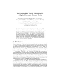
2 All signals are buffered and simultaneously digitized with three high Accuracy , 24-bit ADCs, driven by an internal 15ppm/ C (maximum) reference. Thermocouple Measurement with Automatic Cold Junction CompensationTypical Temperature Error ContributionAPPLICATIONSL, LT, LTC, LTM, Linear Technology and the Linear logo are registered trademarks of Linear Technology Corporation. All other trademarks are the property of their respective owners. Patents Pending nDirectly Digitize RTDs, Thermocouples, Thermistors and Diodes nSingle to Supply nResults Reported in C or F n20 Flexible Inputs Allow Interchanging Sensors nAutomatic Thermocouple Cold Junction Compensation nBuilt-In Standard and User-Programmable Coefficients for Thermocouples, RTDs and Thermistors nConfigurable 2-, 3- or 4-Wire RTD Configurations nMeasures Negative Thermocouple Voltages nAutomatic Burn Out, Short-Circuit and Fault Detection nBuffered Inputs Allow External Protection nSimultaneous 50Hz/60Hz Rejection nIncludes 15ppm/ C (Max) Reference (I-Grade) nDirect Thermocouple Measurements nDirect RTD Measurements nDirect Thermistor Measurements nCustom Sensor Applications2983 TA01a C/ FVREF (10ppm/ C)LTC298324-BIT ADC24-BIT ADC24-BIT TO DETECTIONSPIINTERFACETEMPERATURE ( C)
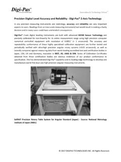
3 200 ( C) DIODELTC298322983fcFor more information OF CONTENTS Features ..1 Applications ..1 Typical Application .. Maximum Ratings ..3 Order Information ..3 Complete System Electrical Characteristics ..3 Pin Configuration ..3 ADC Electrical Characteristics ..4 Reference Electrical Characteristics ..4 Digital Inputs and Digital Outputs ..5 Typical Performance Characteristics ..6 Pin Functions ..9 Block Diagram ..10 Test Circuits ..11 Timing Diagram ..11 Overview ..12 Applications Information ..16 Thermocouple Measurements ..21 Diode Measurements ..24 RTD Measurements ..28 Thermistor Measurements ..43 Direct ADC Measurements ..55 Supplemental Information ..55 Fault Protection and Anti-Aliasing ..572- and 3-Cycle Conversion Modes ..57 Running Conversions Consecutively on Multiple Channels ..58 MUX Configuration Delay.
4 58 Global Configuration Register ..59 Custom Thermocouples ..59 Custom RTDs ..62 Custom Thermistors ..65 Package Description ..70 Revision History ..71 Typical Application ..72 Related Parts ..72 LTC298332983fcFor more information CONFIGURATIONABSOLUTE MAXIMUM RATINGSS upply Voltage (VDD) .. to 6 VAnalog Input Pins (CH1 to CH20, COM) .. to (VDD + )Input Current (CH1 to CH20, COM) .. 15mADigital Inputs (CS, SDI, SCK, RESET) .. to (VDD + ) Digital Outputs (SDO, INTERRUPT) to (VDD + )VREFP .. to , Q2, Q3, LDO, VREFOUT, VREF_ BVP (Note 17)Reference Short-Circuit Duration ..IndefiniteOperating Temperature Range LTC2983C ..0 C to 70 C LTC2983I .. 40 C to 85 C LTC2983H .. 40 C to 125 C(Notes 1, 2)ORDER INFORMATIONLEAD FREE FINISHTRAYPART MARKING*PACKAGE DESCRIPTIONTEMPERATURE RANGELTC2983 CLX#PBFLTC2983 CLX#PBFLTC2983LX48-Lead (7mm 7mm) LQFP0 C to 70 CLTC2983 ILX#PBFLTC2983 ILX#PBFLTC2983LX48-Lead (7mm 7mm) LQFP 40 C to 85 CLTC2983 HLX#PBFLTC2983 HLX#PBFLTC2983LX48-Lead (7mm 7mm) LQFP 40 C to 125 CConsult LTC Marketing for parts specified with wider operating temperature ranges.
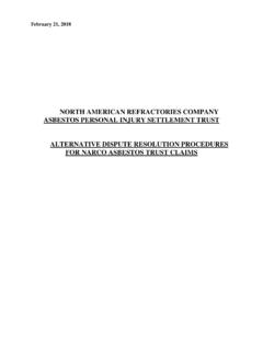
5 *The temperature grade is identified by a label on the shipping more information on lead free part marking, go to: 1314151617181920212223244847464544434241 40393837 VREFOUTVREFPGNDCH1CH2CH3CH4CH5CH6CH7CH8C H9252627282930313233343536CH10CH11CH12CH 13CH14CH15CH16CH17CH18CH19CH20 COM121110987654321 GNDVREF_BYPNCGNDVDDGNDVDDGNDVDDGNDVDDGND Q1Q2Q3 VDDGNDLDORESETCSSDISDOSCKINTERRUPTTOP VIEWLX PACKAGE48-LEAD (7mm 7mm) PLASTIC LQFP TJMAX = 150 C, JA = 57 C/WCOMPLETE SYSTEM ELECTRICAL CHARACTERISTICSPARAMETERCONDITIONSMINTYP MAXUNITSS upply Currentl1520mASleep Currentl2560 AInput RangeAll Analog Input Channelsl RateTwo Conversion Cycle Mode (Notes 6, 9)l150164170msOutput RateThree Conversion Cycle Mode (Notes 6, 9)l225246255msInput Common Mode Rejection50Hz/60Hz (Note 4)l120dBInput Normal Mode Rejection60Hz (Notes 4, 7)l120dB The l denotes the specifications which apply over the full operating temperature range, otherwise specifications are at TA = 25 more information ELECTRICAL CHARACTERISTICSPARAMETERCONDITIONSMINTYP MAXUNITSR esolution (No Missing Codes) FS VIN + FSl24 BitsIntegral NonlinearityVIN(CM) = (Note 15)l230ppm of VREFO ffset VOffset Error Drift(Note 4)l1020nV/ CPositive Full-Scale Error(Notes 3, 15)l100ppm of VREFP ositive Full-Scale Drift(Notes 3, 15) of VREF/ CInput Leakage(Note 18)
6 H-Gradel l1 10nA nANegative Full-Scale Error(Notes 3, 15)l100ppm of VREFN egative Full-Scale Drift(Notes 3, 15) of VREF/ CInput Referred Noise(Note 5) H-Gradel VRMS VRMSC ommon Mode Input Rangel Excitation Current(Note 16)l 25 Table 3025%RTD Excitation Current MatchingContinuously CalibratedlError within Noise Level of ADCT hermistor Excitation Current(Note 16)l The l denotes the specifications which apply over the full operating temperature range, otherwise specifications are at TA = 25 ELECTRICAL CHARACTERISTICSPARAMETERCONDITIONSMINTYP MAXUNITSO utput VoltageVREFOUT (Note 10) Voltage Temperature CoefficientI-Grade, H-Gradel315ppm/ COutput Voltage Temperature CoefficientC-Gradel320ppm/ CLine Regulationl10ppm/VLoad RegulationIOUT(SOURCE) = 100 Al5mV/mAIOUT(SINK) = 100 Al5mV/mAOutput Voltage f 10Hz4 VP-P10Hz f VP-POutput Short-Circuit CurrentShort VREFOUT to GND40mAShort VREFOUT to VDD30mATurn-On Setting, CLOAD = 1 F115 sLong Term Drift of Output Voltage (Note 13)60ppm/ khrHysteresis (Note 14)
7 T = 0 C to 70 C T = 40 C to 85 C30 70ppm ppm The l denotes the specifications which apply over the full operating temperature range, otherwise specifications are at TA = 25 Normal Mode Rejection50Hz (Notes 4, 8)l120dBInput Normal Mode Rejection50Hz/60Hz (Notes 4, 6, 9)l75dBPower-On Reset Power-Up(Note 11)l100msDigital Initialization(Note 12)l100ms The l denotes the specifications which apply over the full operating temperature range.
8 Otherwise specifications are at TA = 25 SYSTEM ELECTRICAL CHARACTERISTICSLTC298352983fcFor more information INPUTS AND Digital OUTPUTSSYMBOLPARAMETERCONDITIONSMINTYPMA XUNITSE xternal SCK Frequency Rangel02 MHzExternal SCK LOW Periodl250nsExternal SCK HIGH Periodl250nst1CS to SDO Validl0200nst2CS to SDO Hi-Zl0200nst3CS to SCK l100nst4 SCK to SDO Validl225nst5 SDO Hold After SCK l10nst6 SDI Setup Before SCK l100nst7 SDI HOLD After SCK l100nsHigh Level Input VoltageCS, SDI, SCK, RESETlVDD Level Input VoltageCS, SDI, SCK, Input CurrentCS, SDI, SCK, RESETl 1010 ADigital Input CapacitanceCS, SDI, SCK, RESET10pFLOW Level Output Voltage (SDO, INTERRUPT)IO = 800 Level Output Voltage (SDO, INTERRUPT)IO = Output Leakage (SDO)l 1010 A The l denotes the specifications which apply over the full operating temperature range, otherwise specifications are at TA = 25 1: Stresses beyond those listed under Absolute Maximum Ratings may cause permanent damage to the device.
9 Exposure to any Absolute Maximum Rating condition for extended periods may affect device reliability and 2: All voltage values are with respect to 3: Full scale ADC error. Measurements do not include reference 4: Guaranteed by design, not subject to 5: The input referred noise includes the contribution of internal calibration 6: MUX configuration delay = default 1msNote 7: Global configuration set to 60Hz 8: Global configuration set to 50Hz 9: Global configuration default 50Hz/60Hz 10: The exact value of VREF is stored in the LTC2983 and used for all measurement calculations. Temperature coefficient is measured by dividing the maximum change in output voltage by the specified temperature 11: Analog power-up. Command status register inaccessible during this 12: Digital initialization. Begins at the conclusion of Analog Power-Up.
10 Command status register is 0 80 at the beginning of Digital initialization and 0 40 at the 13: Long-term stability typically has a logarithmic characteristic and therefore, changes after 1000 hours tend to be much smaller than before that time. Total drift in the second thousand hours is normally less than one third that of the first thousand hours with a continuing trend toward reduced drift with time. Long-term stability will also be affected by differential stresses between the IC and the board material created during board 14: Hysteresis in output voltage is created by package stress that differs depending on whether the IC was previously at a higher or lower temperature. Output voltage is always measured at 25 C, but the IC is cycled to the hot or cold temperature limit before successive measurements. Hysteresis measures the maximum output change for the averages of three hot or cold temperature cycles.