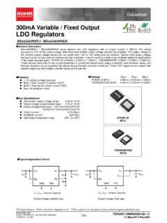
Transcription of LTC3105 - analog.com
1 LTC3105 . 400mA Step-Up DC/DC. Converter with Maximum Power Point Control and 250mV start -Up FEATURES DESCRIPTION. n Low start -Up Voltage: 250mV The LTC 3105 is a high efficiency step-up DC/DC converter n Maximum Power Point Control that can operate from input voltages as low as 225mV. A. n Wide V Range: 225mV to 5V 250mV start -up capability and integrated maximum power IN. n Auxiliary 6mA LDO Regulator point controller (MPPC) enable operation directly from low n Burst Mode Operation: I = 24 A voltage, high impedance alternative power sources such as Q. n Output Disconnect and Inrush current Limiting photovoltaic cells, TEGs (thermoelectric generators) and n V > V. IN OUT Operation fuel cells. A user programmable MPPC set point maximizes n Antiringing Control the energy that can be extracted from any power source. n soft start Burst Mode operation, with a proprietary self adjusting n Automatic Power Adjust peak current , optimizes converter efficiency and output n Power Good Indicator voltage ripple over all operating conditions.
2 N 10-Lead 3mm 3mm DFN and 12-Lead The AUX powered 6mA LDO provides a regulated rail for MSOP Packages external microcontrollers and sensors while the main output is charging. In shutdown, IQ is reduced to 10 A. APPLICATIONS and integrated thermal shutdown offers protection from n Solar Powered Battery/Supercapacitor Chargers overtemperature faults. The LTC3105 is offered in 10-lead n Energy Harvesting 3mm 3mm DFN and 12-lead MSOP packages. n Remote Industrial Sensors L, LT, LTC, LTM, Linear Technology, the Linear logo and Burst Mode are registered trademarks n and ThinSOT and PowerPath are trademarks of Linear Technology Corporation. All other Low Power Wireless Transmitters trademarks are the property of their respective owners. n Cell Phone, MP3, PMP and GPS Accessory Chargers TYPICAL APPLICATION. Single Photovoltaic Cell Li-Ion Trickle Charger Output current vs Input Voltage 10 H 80. MPPC DISABLED. 70. 225mV TO 5V. VIN SW VOUT = 60. +. OUTPUT current (mA). VOUT. PHOTOVOLTAIC VOUT.
3 10 F 50. CELL LTC3105 VOUT = 1020k 40. FB VOUT = 5V. Li-Ion 30. MPPC PGOOD 332k OFF ON SHDN LDO 20. 10 F. AUX FBLDO 10. 1 F GND F 0. 3105 TA01a INPUT VOLTAGE (V). 3105 TA01b 3105fb For more information 1. LTC3105 . ABSOLUTE MAXIMUM RATINGS (Note 1). SW Voltage Maximum Junction Temperature (Note 4).. 125 C. to 6V Storage 65 C to 150 C. Pulsed (<100ns).. 1V to 7V Lead Temperature (Soldering, 10 sec.). Voltage, All Other to 6V MS 300 C. Operating Junction Temperature Range (Note 2).. 40 C to 85 C. PIN CONFIGURATION. TOP VIEW. TOP VIEW. FB 1 10 AUX 1. FB 12 AUX. LDO 2 9 VOUT LDO 2 11 VOUT. 11. FBLDO 3 8 PGOOD FBLDO 3 10 PGOOD. GND. SHDN 4 7 SW SHDN 4 9 SW. MPPC 5 8 VIN. MPPC 5 6 VIN 6. GND 7 GND. DD PACKAGE MS PACKAGE. 10-LEAD (3mm 3mm) PLASTIC DFN 12-LEAD PLASTIC MSOP. TJMAX = 125 C, JA = 43 C/W, JC = 3 C/W TJMAX = 125 C, JA = 130 C/W, JC = 21 C/W. EXPOSED PAD (PIN 11) IS GND, MUST BE SOLDERED TO PCB. ORDER INFORMATION. LEAD FREE FINISH TAPE AND REEL PART MARKING PACKAGE DESCRIPTION TEMPERATURE RANGE.
4 LTC3105 EDD#PBF LTC3105 EDD#TRPBF LFQC 10-Lead (3mm 3mm) Plastic DFN 40 C to 85 C. LTC3105 EMS#PBF LTC3105 EMS#TRPBF 3105 12-Lead Plastic MSOP 40 C to 85 C. Consult LTC Marketing for parts specified with wider operating temperature ranges. Consult LTC Marketing for information on non-standard lead based finish parts. For more information on lead free part marking, go to: For more information on tape and reel specifications, go to: 3105fb 2 For more information LTC3105 . ELECTRICAL. The CHARACTERISTICS l denotes the specifications which apply over the full operating junction temperature range, otherwise specifications are at TA = 25 C (Note 2). VAUX = VOUT = , VLDO = , VIN = , unless otherwise noted. PARAMETER CONDITIONS MIN TYP MAX UNITS. Step-Up Converter Input Operating Voltage l 5 V. Input start -Up Voltage (Note 5) l V. TJ = 0 C to 85 C (Note 5) V. Output Voltage Adjust Range l V. Feedback Voltage (FB Pin) l V. VOUT IQ in Operation VFB = 24 A. VOUT IQ in Shutdown SHDN = 0V 10 A.
5 MPPC Pin Output current VMPPC = 10 A. SHDN Input Logic High Voltage l V. SHDN Input Logic Low Voltage l V. N-Channel SW Pin Leakage current VIN = VSW = 5V, VSHDN = 0V 1 10 A. P-Channel SW Pin Leakage current VIN = VSW = 0V, VOUT = VAUX = 1 10 A. N-Channel On-Resistance: SW to GND . P-Channel On-Resistance: SW to VOUT . Peak current Limit VFB = , VMPPC = (Note 3) A. Valley current Limit VFB = , VMPPC = (Note 3) A. PGOOD Threshold (% of Feedback Voltage) VOUT Falling 85 90 95 %. LDO Regulator LDO Output Adjust Range External Feedback Network, VAUX > VLDO l 5 V. LDO Output Voltage VFBLDO = 0V l V. Feedback Voltage (FBLDO Pin) External Feedback Network l V. Load Regulation ILDO = 1mA to 6mA %. Line Regulation VAUX = to 5V %. Dropout Voltage ILDO = 6mA, VOUT = VAUX = 105 mV. LDO current Limit VLDO Below Regulation Voltage l 6 12 mA. LDO Reverse-Blocking Leakage current VIN = VAUX = VOUT = 0V, VSHDN = 0V 1 A. Note 1: Stresses beyond those listed under Absolute Maximum Ratings Note 3: current measurements are performed when the LTC3105 is not may cause permanent damage to the device.
6 Exposure to any Absolute switching. The current limit values measured in operation will be somewhat Maximum Rating condition for extended periods may affect device higher due to the propagation delay of the comparators. reliability and lifetime. Note 4: This IC includes over temperature protection that is intended Note 2: The LTC3105 is tested under pulsed load conditions such that to protect the device during momentary overload conditions. Junction TJ TA. The LTC3105E is guaranteed to meet specifications from temperature will exceed 125 C when overtemperature protection is active. 0 C to 85 C junction temperature. Specifications over the 40 C to 85 C Continuous operation above the specified maximum operating junction operating junction temperature range are assured by design, character- temperature may impair device reliability. ization and correlation with statistical process controls. Note that the Note 5: The LTC3105 has been optimized for use with high impedance maximum ambient temperature consistent with these specifications is power sources such as photovoltaic cells and thermoelectric generators.
7 Determined by specific operating conditions in conjunction with board The input start -up voltage is measured using an input voltage source with layout, the rated package thermal impedance and other environmental a series resistance of approximately 200m and MPPC enabled. Use of the factors. LTC3105 with lower resistance voltage sources or with MPPC disabled may result in a higher input start -up voltage. 3105fb For more information 3. LTC3105 . TYPICAL. T PERFORMANCE CHARACTERISTICS A = 25 C, VAUX = VOUT = , VLDO = , VIN = , unless otherwise noted. Minimum Input start -Up Voltage Shutdown Thresholds vs Temperature vs Input Voltage IC Enable Delay vs Input Voltage 340 1000 120. 900. 320 IC ENABLE. 800. THRESHOLD VOLTAGE (mV). 100. 300. INPUT VOLTAGE (mV). 700. DELAY TIME ( s). 280 600. IC DISABLE. 500 80. 260. 400. 240 300. 60. 200. 220. 100. 200 0 40. 45 30 15 0 15 30 45 60 75 90 TEMPERATURE ( C) SUPPLY VOLTAGE, VIN OR VAUX (V) SUPPLY VOLTAGE, VIN OR VAUX (V). 3105 G01 3105 G02 3105 G03.
8 MPPC current Variation ldo soft - start Duration vs Temperature vs LDO Load CHANGE FROM 25 C (%). soft - start TIME (ms). 0. 45 30 15 0 15 30 45 60 75 90 1 2 3 4 5 6. TEMPERATURE ( C) 3105 G05. LDO LOAD current (mA). 3105 G06. VOUT IQ vs Temperature During Shutdown VIN for Synchronous Operation 22 SHDN = 0V. 20 NONSYNCHRONOUS. MAXIMUM INPUT VOLTAGE (V). 18 OPERATION. 16 14. IQ ( A). 12. 10 SYNCHRONOUS. OPERATION. 8 6 4 0. 45 30 15 0 15 30 45 60 75 90 TEMPERATURE ( C) 3105 G07. OUTPUT VOLTAGE (V). 3105 G09. 3105fb 4 For more information LTC3105 . TYPICAL. T PERFORMANCE CHARACTERISTICS A = 25 C, VAUX = VOUT = , VLDO = , VIN = , unless otherwise noted. Exiting MPPC Control on IPEAK and IVALLEY current Limit Input Voltage Step Change vs Temperature Efficiency vs VIN. 100. VIN VOLTAGE VMPPC = 400mV VOUT = 3V. IPEAK ILOAD = 10mA. 200mV/DIV. LDO = 90. CHANGE FROM 25 C (%). 0. 80. EFFICIENCY (%). INDUCTOR IVALLEY. current 100mA/DIV 70. MPPC VOLTAGE. 60. 200mV/DIV 50. 40. 15 s/DIV 3105 G10.
9 45 30 15 0 15 30 45 60 75 90 TEMPERATURE ( C) INPUT VOLTAGE (V). 3105 G11 3105 G12. Efficiency vs Output current and Input and Output Burst Ripple Power Loss, VOUT = 90 1000. VIN = VOUT = VIN = EFFICIENCY. CIN = 470 F IOUT = 15mA 80 VIN = COUT = 10 F VIN = 1V. 70. OUTPUT 100. VOLTAGE. POWER LOSS (mW). 60. EFFICIENCY (%). 50mV/DIV. 50. SW current 10. 200mA/DIV 40. POWER LOSS. 30. 1. 20. INPUT. VOLTAGE 10. 5mV/DIV. 0 50 s/DIV 1 10 100. 3105 G13. OUTPUT current (mA) 3105 G14. Efficiency vs Output current and No-Load Input current Power Loss, VOUT = 5V vs Input Voltage 100 1000 800. VIN = 3V VOUT = 90 VIN = 2V 700. VIN = 80 100 600. INPUT current ( A). POWER LOSS (mW). EFFICIENCY. EFFICIENCY (%). 70 500. 60 10 400. 50 300. POWER LOSS. 40 1 200. 30 100. 20 0. 1 10 100 OUTPUT current (mA) 3105 G15. INPUT VOLTAGE (V). 3105 G16. 3105fb For more information 5. LTC3105 . PIN FUNCTIONS (DFN/MSOP). FB (Pin 1/Pin 1): Step-Up Converter Feedback Input. GND (Exposed Pad Pin 11/Pins 6, 7) : Small Signal and Connect the VOUT resistor divider tap to this input.
10 The Power Ground for the IC. The GND connections should be output voltage can be adjusted between and soldered to the PCB ground using the lowest impedance LDO (Pin 2/Pin 2): LDO Regulator Output. Connect a F path possible. or larger capacitor between LDO and GND. SW (Pin 7/Pin 9): Switch Pin. Connect an inductor between FBLDO (Pin 3/Pin 3): LDO Feedback Input. Connect the SW and VIN. PCB trace lengths should be as short as pos- sible to reduce EMI. While the converter is sleeping or is LDO resistive divider tab to this input. Alternatively, con- necting FBLDO directly to GND will configure the LDO in shutdown, the internal antiringing switch connects the output voltage to be internally set at (nominal). SW pin to the VIN pin in order to minimize EMI. PGOOD (Pin 8/Pin 10): Power Good Indicator. This is an SHDN (Pin 4/Pin 4): Logic Controlled Shutdown Input. open-drain output. The pull-down is disabled when VOUT. With SHDN open, the converter is enabled by an internal has achieved the voltage defined by the feedback divider 2M pull-up resistor.