Transcription of LTC4000 - High Voltage High Current Controller for …
1 LTC4000 . high Voltage high Current Controller for Battery Charging and Power Management Features Description n Complete high Performance Battery Charger When The LTC 4000 is a high Voltage , high performance Controller Paired with a DC/DC Converter that converts many externally compensated DC/DC power n Wide Input and Output Voltage Range: 3V to 60V supplies into full-featured battery chargers. n Input Ideal Diode for Low Loss Reverse Blocking Features of the LTC4000 's battery charger include: accurate and Load Sharing n Output Ideal Diode for Low Loss PowerPath and ( ) programmable float Voltage , selectable timer or Current termination, temperature qualified charging using Load Sharing with the Battery n Instant-On Operation with Heavily Discharged an NTC thermistor, automatic recharge, C/10 trickle charge for deeply discharged cells, bad battery detection and Battery n Programmable Input and Charge Current : status indicator outputs.
2 The battery charger also includes precision Current sensing that allows lower sense voltages 1% Accuracy n Accurate Programmable Float Voltage for high Current applications. n Programmable C/X or Timer Based Charge The LTC4000 supports intelligent PowerPath control. An Termination external PFET provides low loss reverse Current protec- n NTC Input for Temperature Qualified Charging tion. Another external PFET provides low loss charging n 28-Lead 4mm 5mm QFN or SSOP Packages or discharging of the battery. This second PFET also facilitates an instant-on feature that provides immediate downstream system power even when connected to a Applications heavily discharged or short faulted battery. n high Power Battery Charger Systems n high Performance Portable Instruments The LTC4000 is available in a low profile 28-lead 4mm.
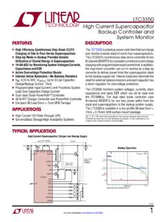
3 N Industrial Battery Equipped Devices 5mm QFN and SSOP packages. n Notebook/Subnotebook Computers L, LT, LTC, LTM, Linear Technology and the Linear logo are registered trademarks and PowerPath is a trademark of Linear Technology Corporation. All other trademarks are the property of their respective owners. Typical Application 48V to at 10A Buck Converter Charger for Three LiFePO4 Cells Charge Current and VOUT Profile Si7135DP. vs VBAT During a Charge Cycle LT3845A VOUT. 15V TO 60V IN OUT. SHDN VC 12V, 15A 12 11. 5m 100 F. 5m ICHARGE VOUT. 47nF 10 ITH CC IID IGATE CSP. RST CSN 8 VOUT 10. CLN. ICHARGE (A). BGATE Si7135DP. VOUT (V). IN 6 BAT. 1 F. OFB. 127k 4 9. VM. LTC4000 . 100k ENC FBG. VBAT 2 ICHARGE CHRG 133k FLOAT. FLT BFB 10A MAX CHARGE 0 8. IIMON Current .
4 NTC 6 7 8 9 10 11 12. 10nF IBMON VBAT (V). 10nF TMR CL CX GND BIAS 10k 3-CELL LiFePO4. 4000 TA01b 10k BATTERY PACK. F 1 F. 4000 TA01a NTHS0603. N02N1002J. 4000fb For more information 1. LTC4000 . Absolute Maximum Ratings (Note 1). IN, CLN, IID, CSP, CSN, to 62V to Min (6V, VIN). IN-CLN, 1V to 1V to Min (VBIAS, VCSP). OFB, BFB, to 62V to 6V. 1mA to 2mA CHRG, FLT, to 62V. (VIID, VCSP) 10V to Max (VIID, VCSP) CHRG, FLT, 1mA to 2mA. (VBAT, VCSN) 10V to Max (VBAT, VCSN) Operating Junction Temperature Range ENC, CX, NTC, to VBIAS (Note 2).. 125 C. IL, CL, TMR, IIMON, to VBIAS Storage Temperature 65 C to 150 C. Pin Configuration TOP VIEW. TOP VIEW. ENC 1 28 IL. GND. CLN. ITH. IBMON 2 27 IIMON. IID. CC. IN. 28 27 26 25 24 23 CX 3 26 RST. VM 1 22 IGATE CL 4 25 VM.
5 RST 2 21 OFB 5 24 GND. TMR. IIMON 3 20 CSP. GND 6 23 IN. IL 4 29 19 CSN. FLT 7 22 CLN. ENC 5 GND 18 BGATE. CHRG 8 21 CC. IBMON 6 17 BAT. BIAS 9 20 ITH. CX 7 16 BFB. NTC 10 19 IID. CL 8 15 FBG. FBG 11 18 IGATE. 9 10 11 12 13 14. BFB 12 17 OFB. TMR. GND. FLT. CHRG. BIAS. NTC. BAT 13 16 CSP. UFD PACKAGE BGATE 14 15 CSN. 28-LEAD (4mm 5mm) PLASTIC QFN. TJMAX = 125 C, JA = 43 C/W, JC = 4 C/W GN PACKAGE. EXPOSED PAD (PIN 29) IS GND, MUST BE SOLDERED TO PCB 28-LEAD PLASTIC SSOP. TJMAX = 125 C, JA = 80 C/W, JC = 25 C/W. Order Information LEAD FREE FINISH TAPE AND REEL PART MARKING* PACKAGE DESCRIPTION TEMPERATURE RANGE. LTC4000 EUFD#PBF LTC4000 EUFD#TRPBF 4000 28-Lead (4mm 5mm) Plastic QFN 40 C to 125 C. LTC4000 IUFD#PBF LTC4000 IUFD#TRPBF 4000 28-Lead (4mm 5mm) Plastic QFN 40 C to 125 C.
6 LTC4000 EGN#PBF LTC4000 EGN#TRPBF LTC4000GN 28-Lead Plastic SSOP 40 C to 125 C. LTC4000 IGN#PBF LTC4000 IGN#TRPBF LTC4000GN 28-Lead Plastic SSOP 40 C to 125 C. Consult LTC Marketing for parts specified with wider operating temperature ranges. *The temperature grade is identified by a label on the shipping container. Consult LTC Marketing for information on non-standard lead based finish parts. For more information on lead free part marking, go to: For more information on tape and reel specifications, go to: 4000fb 2 For more information LTC4000 . Electrical Characteristics The l denotes the specifications which apply over the full operating junction temperature range, otherwise specifications are at TA = 25 C. VIN = VCLN = 3V to 60V unless otherwise noted (Notes 2, 3).
7 SYMBOL PARAMETER CONDITIONS MIN TYP MAX UNITS. VIN Input Supply Operating Range l 3 60 V. IIN Input Quiescent Operating Current mA. IBAT Battery Pin Operating Current VIN 3V, VCSN = VCSP VBAT l 50 100 A. Battery Only Quiescent Current VIN = 0V, VCSN = VCSP VBAT l 10 20 A. Shutdown ENC Input Voltage Low l V. ENC Input Voltage high l V. ENC Pull-Up Current VENC = 0V 4 2 A. ENC Open Circuit Voltage VENC = Open l V. Voltage Regulation VBFB_REG Battery Feedback Voltage V. l V. BFB Input Current VBFB = A. VOFB_REG Output Feedback Voltage l V. OFB Input Current VOFB = A. RFBG Ground Return Feedback Resistance l 100 400 . VRECHRG(RISE) Rising Recharge Battery Threshold Voltage % of VBFB_REG l %. VRECHRG(HYS) Recharge Battery Threshold Voltage Hysteresis % of VBFB_REG %.
8 VOUT(INST_ON) Instant-On Battery Voltage Threshold % of VBFB_REG l 82 86 90 %. VLOBAT Falling Low Battery Threshold Voltage % of VBFB_REG l 65 68 71 %. VLOBAT(HYS) Low Battery Threshold Voltage Hysteresis % of VBFB_REG 3 %. Current Regulation Ratio of Monitored- Current Voltage to Sense VIN,CLN 50mV, VIIMON/VIN,CLN l 20 21 V/V. Voltage VCSP,CSN 50mV, VIBMON/VCSP,CSN. VOS Sense Voltage Offset VCSP,CSN 50mV, VCSP = 60V or VIN,CLN 50mV, VIN = 60V (Note 4) 300 300 V. CLN, CSP, CSN Common Mode Range (Note 4) l 3 60 V. CLN Pin Current 1 A. CSP Pin Current VIGATE = Open, VIID = 0V 90 A. CSN Pin Current VBGATE = Open, VBAT = 0V 45 A. IIL Pull-Up Current for the Input Current Limit l 55 50 45 A. Programming Pin ICL Pull-Up Current for the Charge Current Limit l 55 50 45 A.
9 Programming Pin ICL_TRKL Pull-Up Current for the Charge Current Limit VBFB < VLOBAT l A. Programming Pin in Trickle Charge Mode Input Current Monitor Resistance to GND 40 90 140 k . Charge Current Monitor Resistance to GND 40 90 140 k . A4, A5 Error Amp Offset for the Current Loops VCL = , VIL = l 10 0 10 mV. (See Figure 1). Maximum Programmable Current Limit l V. Voltage Range 4000fb For more information 3. LTC4000 . Electrical Characteristics The l denotes the specifications which apply over the full operating junction temperature range, otherwise specifications are at TA = 25 C. VIN = VCLN = 3V to 60V unless otherwise noted (Notes 2, 3). SYMBOL PARAMETER CONDITIONS MIN TYP MAX UNITS. Charge Termination CX Pin Pull-Up Current VCX = l A. VCX,IBMON(OS) CX Comparator Offset Voltage , IBMON Falling VCX = l 10 25 mV.
10 VCX,IBMON(HYS) CX Comparator Hysteresis Voltage 5 mV. TMR Pull-Up Current VTMR = 0V A. TMR Pull-Down Current VTMR = 2V A. TMR Pin Frequency CTMR = F 400 500 600 Hz TMR Threshold for CX Termination l V. tT Charge Termination Time CTMR = F l h tT/tBB Ratio of Charge Terminate Time to Bad Battery CTMR = F l 4 h/h Indicator Time VNTC(COLD) NTC Cold Threshold VNTC Rising, % of VBIAS l 73 75 77 %. VNTC(HOT) NTC Hot Threshold VNTC Falling, % of VBIAS l 33 35 37 %. VNTC(HYS) NTC Thresholds Hysteresis % of VBIAS 5 %. VNTC(OPEN) NTC Open Circuit Voltage % of VBIAS l 45 50 55 %. RNTC(OPEN) NTC Open Circuit Input Resistance 300 k . Voltage Monitoring and Open Drain Status Pins VVM(TH) VM Input Falling Threshold l V. VVM(HYS) VM Input Hysteresis 40 mV. VM Input Current VVM = A.