Transcription of LTC4446 - High Voltage High Side / Low Side N …
1 LTC444614446fTYPICAL APPLICATIONFEATURESAPPLICATIONSDESCRIPTI ONHigh Voltage High side / low side N-Channel MOSFET DriverThe LTC 4446 is a high frequency high Voltage gate driver that drives two N-channel MOSFETs in a DC/DC converter with supply voltages up to 100V. The powerful driver ca-pability reduces switching losses in MOSFETs with high gate capacitance. The LTC4446 s pull-up for the top gate driver has a peak output current of and its pull-down has an output impedance of . The pull-up for the bot-tom gate driver has a peak output current of 3A and the pull-down has an output impedance of .The LTC4446 is confi gured for two supply-independent inputs. The high side input logic signal is internally level-shifted to the bootstrapped supply, which may function at up to 114V above ground. The LTC4446 contains undervoltage lockout circuits that disable the external MOSFETs when activated. The LTC4446 is available in the thermally enhanced 8-lead MSOP LTC4446 does not have adaptive shoot-through pro-tection.
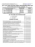
2 For similar drivers with adaptive shoot-through protection, please refer to the chart ProtectionNoYesYesAbsolute Max TS100V100V100 VMOSFET Gate to to to UV+ UV Bootstrap Supply Voltage Up to 114Vn Wide VCC Voltage : to Peak Top Gate Pull-Up Currentn 3A Peak Bottom Gate Pull-Up Currentn Top Gate Driver Pull-Downn Bottom Gate Driver Pull-Downn 5ns Top Gate Fall Time Driving 1nF Loadn 8ns Top Gate Rise Time Driving 1nF Loadn 3ns Bottom Gate Fall Time Driving 1nF Loadn 6ns Bottom Gate Rise Time Driving 1nF Loadn Drives Both High and low side N-Channel MOSFETsn Undervoltage Lockoutn Thermally Enhanced 8-Pin MSOP Packagen Distributed Power Architecturesn Automotive Power Suppliesn High Density Power Modulesn Telecommunication SystemsTwo Switch Forward ConverterLTC4446 Driving a 1000pF Capacitive LoadL, LT, LTC and LTM are registered trademarks of Linear Technology Corporation. All other trademarks are the property of their respective owners.
3 Protected by Patents including TO 72V(100V ABS MAX)GNDTSVCCTOSECONDARYCIRCUIT TINPLTC4446 BGPWM2(FROM CONTROLLER IC)PWM1(FROM CONTROLLER IC) TO TA01a BINP5V/DIVBG10V/DIVTINP5V/DIVTG-TS10V/DI V20ns/DIV4446 TA01bLTC444624446fPIN CONFIGURATIONABSOLUTE MAXIMUM RATINGSS upply Voltage VCC .. to 14V BOOST TS .. to 14 VTINP Voltage .. 2V to 14 VBINP Voltage .. 2V to 14 VBOOST Voltage .. to 114 VTS Voltage .. 5V to 100 VOperating Temperature Range (Note 2).. 40 C to 85 CJunction Temperature (Note 3) .. 125 CStorage Temperature Range .. 65 C to 150 CLead Temperature (Soldering, 10 sec) .. 300 C(Note 1)1234 TINPBINPVCCBG8765 TSTGBOOSTNCTOP VIEW9MS8E PACKAGE8-LEAD PLASTIC MSOPTJMAX = 125 C, JA = 40 C/W, JC = 10 C/W (NOTE 4)EXPOSED PAD (PIN 9) IS GND, MUST BE SOLDERED TO PCBORDER INFORMATIONELECTRICAL CHARACTERISTICSSYMBOLPARAMETERCONDITIONS MINTYPMAXUNITSGate Driver Supply, VCCVCCO perating Supply Current TINP = BINP = 0V350550 AUVLOU ndervoltage Lockout ThresholdVCC RisingVCC Supply (BOOST TS)IBOOSTDC Supply CurrentTINP = BINP = AInput Signal (TINP, BINP)VIH(BG)BG Turn-On Input ThresholdBINP Ramping (BG)BG Turn-Off Input ThresholdBINP Ramping (TG)TG Turn-On Input ThresholdTINP Ramping (TG)TG Turn-Off Input ThresholdTINP Ramping (BINP)Input Pin Bias Current 2 AHigh side Gate Driver Output (TG)VOH(TG)TG High Output VoltageITG = 10mA, VOH(TG) = VBOOST (TG)TG Low Output VoltageITG = 100mA, VOL(TG) = VTG VTSl120220mVIPU(TG)TG Peak Pull-Up (TG)
4 TG Pull-Down The l denotes the specifi cations which apply over the full operating temperature range, otherwise specifi cations are at TA = 25 C. VCC = VBOOST = 12V, VTS = GND = 0V, unless otherwise FREE FINISHTAPE AND REELPART MARKING*PACKAGE DESCRIPTIONTEMPERATURE RANGELTC4446 EMS8E#PBFLTC4446 EMS8E#TRPBFLTDPZ8-Lead Plastic MSOP 40 C to 85 CLTC4446 IMS8E#PBFLTC4446 IMS8E#TRPBFLTDPZ8-Lead Plastic MSOP 40 C to 85 CConsult LTC Marketing for parts specifi ed with wider operating temperature ranges. *The temperature grade is identifi ed by a label on the shipping LTC Marketing for information on non-standard lead based fi nish more information on lead free part marking, go to: For more information on tape and reel specifi cations, go to: 1: Stresses beyond those listed under Absolute Maximum Ratings may cause permanent damage to the device.
5 Exposure to any Absolute Maximum Rating condition for extended periods may affect device reliability and 2: The LTC4446E is guaranteed to meet specifi cations from 0 C to 85 C. Specifi cations over the 40 C to 85 C operating temperature range are assured by design, characterization and correlation ELECTRICAL CHARACTERISTICS The l denotes the specifi cations which apply over the full operating temperature range, otherwise specifi cations are at TA = 25 C. VCC = VBOOST = 12V, VTS = GND = 0V, unless otherwise side Gate Driver Output (BG)VOH(BG)BG High Output VoltageIBG = 10mA, VOH(BG) = VCC (BG)BG Low Output VoltageIBG = 100mAl55110mVIPU(BG)BG Peak Pull-Up Currentl23 ARDS(BG)BG Pull-Down Switching Time (BINP (TINP) is Tied to Ground While TINP (BINP) is Switching.)
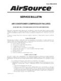
6 Refer to Timing Diagram)tPLH(TG)TG Low-High (Turn-On) Propagation Delayl2545nstPHL(TG)TG High-Low (Turn-Off) Propagation Delayl2240nstPLH(BG)BG Low-High (Turn-On) Propagation Delayl1935nstPHL(BG)BG High-Low (Turn-Off) Propagation Delayl1430nstDM(BGTG)Delay Matching BG Turn-Off and TG Turn-Onl 151035nstDM(TGBG)Delay Matching TG Turn-Off and BG Turn-Onl 25 325nstr(TG)TG Output Rise Time10% 90%, CL = 1nF10% 90%, CL = 10nF880nsnstf(TG)TG Output Fall Time10% 90%, CL = 1nF10% 90%, CL = 10nF550nsnstr(BG)BG Output Rise Time10% 90%, CL = 1nF10% 90%, CL = 10nF660nsnstf(BG)BG Output Fall Time10% 90%, CL = 1nF10% 90%, CL = 10nF330nsnswith statistical process controls. The LTC4446I is guaranteed over the full 40 C to 85 C operating temperature 3: TJ is calculated from the ambient temperature TA and power dissipation PD according to the following formula: TJ = TA + (PD JA C/W)Note 4: Failure to solder the exposed back side of the MS8E package to the PC board will result in a thermal resistance much higher than 40 PERFORMANCE CHARACTERISTICSVCC Supply Quiescent Current vs VoltageBOOST-TS Supply Quiescent Current vs VoltageVCC Supply Current vs TemperatureVCC SUPPLY Voltage (V)00 QUIESCENT CURRENT ( A)501502002506 7 8 9 10 11 12 134504446 G011001234514300350400 TINP = BINP = 0 VTINP(BINP) = 12 VTA = 25 CBOOST = 12 VTS = GNDBOOST SUPPLY Voltage (V)00 QUIESCENT CURRENT ( A)501502002506 7 8 9 101112134004446 G021001234514300350 TINP = BINP = 0 VTINP = 0V, BINP = 12 VTINP = 12V, BINP = 0 VTA = 25 CVCC = 12 VTS = GNDTEMPERATURE ( C)VCC SUPPLY CURRENT ( A)3503603704446 G03330300 40 25 10 5 20 35 50 65 80 95 110125380340320310 TINP = BINP = 0 VVCC = BOOST = 12 VTS = GNDTINP(BINP)
7 = 12 VLTC444644446fTYPICAL PERFORMANCE CHARACTERISTICSB oost Supply Current vs TemperatureOutput Low Voltage (VOL) vs Supply VoltageOutput High Voltage (VOH) vs Supply VoltageInput Thresholds (TINP, BINP) vs Supply VoltageInput Thresholds (TINP, BINP) vs TemperatureInput Thresholds (TINP, BINP) Hysteresis vs VoltageInput Thresholds (TINP, BINP) Hysteresis vs TemperatureVCC Undervoltage Lockout Thresholds vs TemperatureRise and Fall Time vs VCC Supply VoltageTEMPERATURE ( C)BOOST SUPPLY CURRENT ( A)2503003504446 G041500 40 25 10 5 20 35 50 65 80 95 11012540020010050 TINP = 12 VBINP = 0 VTINP = 0 VBINP = 12 VTINP = BINP = 0 VVCC = BOOST = 12 VTS = GNDSUPPLY Voltage (V)7 OUTPUT Voltage (mV)140104446 G058040891120016012010060121314 VOL(TG)VOL(BG)TA = 25 CITG(BG) = 100mABOOST = VCCTS = GNDSUPPLY Voltage (V)75TG OR BG OUTPUT Voltage (V)689101512911124446 G06713 1mA14118101314TA = 25 CBOOST = VCCTS = GND 10mA 100mASUPPLY Voltage (V) OR BG INPUT THRESHOLD (V) = 25 CBOOST = VCCTS = GNDVIH(TG,BG)VIL(TG,BG)TEMPERATURE ( C) 25TG OR BG INPUT THRESHOLD (V) 10 40110205080125 VCC = BOOST = 12 VTS = GNDVIH(TG,BG)VIL(TG,BG)SUPPLY Voltage (V)78375TG OR BG INPUT THRESHOLD HYSTERESIS (mV)425500911124446 G09400475450101314TA = 25 CVCC = BOOSTTS = GNDTEMPERATURE ( C) 40 25375TG OR BG INPUT THRESHOLD HYSTERESIS (mV)425500 10 5 2050 65804446 G104004754503511095125 VCC = BOOST = 12 VTS = GNDTEMPERATURE ( C) SUPLLY Voltage (V) 2535654446 1055080 RISING THRESHOLDFALLING THRESHOLDBOOST = VCCTS = GNDSUPPLY Voltage (V)7 RISE/FALL TIME (ns)122830222632911124446 G12820161024618148101314TA = 25 CBOOST = VCCTS = GNDCL = (TG)tr(BG)tf(TG)tf(BG)LTC444654446fTYPIC AL PERFORMANCE CHARACTERISTICSRise and Fall Time vs Load CapacitancePeak Driver (TG, BG)
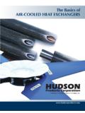
8 Pull-Up Current vs TemperatureOutput Driver Pull-Down Resistance vs TemperaturePropagation Delay vs VCC Supply VoltagePropagation Delay vs Temperature LOAD CAPACITANCE (nF)1 RISE/FALL TIME (ns)40506094445 G1330200357210468108070tr(TG)tr(BG)tf(TG )tf(BG)TA = 25 CVCC = BOOST = 12 VTS = GNDTEMPERATURE ( C) CURRENT (A) 2535654446 1055080 VCC = BOOST = 12 VTS = GNDIPU(BG)IPU(TG)TEMPERATURE ( C) 25 OUTPUT DRIVER PULL-DOWN RESISTACNE ( ) 10 40110205080125 BOOST-TS = 12 VVCC = 12 VVCC = 14 VVCC = 7 VRDS(TG)RDS(BG)BOOST-TS = 14 VBOOST-TS = 7 VSUPPLY Voltage (V)710 PROPAGATION DELAY (ns)121618203024911124444 G16142628228101314TA = 25 CBOOST = VCCTS = GNDtPLH(TG)tPLH(BG)tPHL(BG)tPHL(TG)TEMPE RATURE ( C) 402 PROPAGATION DELAY (ns)717222737 2535654446 G1712322095125110 1055080 VCC = BOOST = 12 VTS = GNDtPLH(TG)tPHL(TG)tPLH(BG)tPHL(BG)Switc hing Supply Current vs Input FrequencySwitching Supply Current vs Load CapacitanceSWITCHING FREQUENCY (kHz)0 SUPPLY CURRENT (mA) (TG SWITCHING)IBOOST(BG SWITCHING)IVCC(BG SWITCHING)IVCC(TG SWITCHING)TA = 25 CVCC = BOOST = 12 VTS = GNDLOAD CAPACITANCE (nF)1 SUPPLY CURRENT (mA) G19 IVCC(BG SWITCHINGAT 1 MHz)IBOOST(TG SWITCHINGAT 500kHz)IBOOST(TG SWITCHINGAT 1 MHz)IBOOST(BG SWITCHING AT 1 MHz OR 5 OOkHz)IVCC(BG SWITCHINGAT 500kHz)IVCC(TG SWITCHING AT 500kHz)IVCC(TG SWITCHINGAT 1 MHz)LTC444664446fPIN FUNCTIONSBLOCK DIAGRAMTINP (Pin 1): High side Input Signal.
9 Input referenced to GND. This input controls the high side driver output (TG).BINP (Pin 2): low side Input Signal. This input controls the low side driver output (BG). VCC (Pin 3): Supply. This pin powers input buffers, logic and the low side gate driver output directly and the high side gate driver output through an external diode con-nected between this pin and BOOST (Pin 6). A low ESR ceramic bypass capacitor should be tied between this pin and GND (Pin 9).BG (Pin 4): low side Gate Driver Output (Bottom Gate). This pin swings between VCC and (Pin 5): No Connect. No connection (Pin 6): High side Bootstrapped Supply. An ex-ternal capacitor should be tied between this pin and TS (Pin 8). Normally, a bootstrap diode is connected between VCC (Pin 3) and this pin. Voltage swing at this pin is from VCC VD to VIN + VCC VD, where VD is the forward volt-age drop of the bootstrap (Pin 7): High side Gate Driver Output (Top Gate).
10 This pin swings between TS and (Pin 8): High side MOSFET Source Connection (Top Source).Exposed Pad (Pin 9): Ground. Must be soldered to PCB ground for optimal thermal DIAGRAM3679 HIGH SIDELEVEL SHIFTERVCC TO 100 VTG8 TSBG4446 BD1 TINPBINP25 NCLOW SIDELEVEL SHIFTERVCCVCC490%INPUT RISE/FALL TIME < 10nsTINP (BINP)BG (TG)BINP (TINP)TG (BG)90%90%trtftPHLtPLH10%4444 TD10%10%LTC444674446fOPERATIONO verviewThe LTC4446 receives ground-referenced, low Voltage digi-tal input signals to drive two N-channel power MOSFETs in a synchronous buck power supply confi guration. The gate of the low side MOSFET is driven either to VCC or GND, depending on the state of the input. Similarly, the gate of the high side MOSFET is driven to either BOOST or TS by a supply bootstrapped off of the switching node (TS).Input StageThe LTC4446 employs CMOS compatible input thresholds that allow a low Voltage digital signal to drive standard power MOSFETs.