Transcription of MOS Capacitor - Chenming Hu
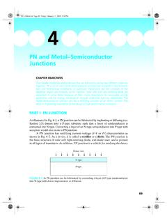
1 1575 MOS CapacitorCHAPTER OBJECTIVESThis chapter builds a deep understanding of the modern MOS(metal oxide semiconductor) structures. The key topics are the concepts of surfacedepletion, threshold, and inversion; MOS Capacitor C V; gate depletion; inversion-layerthickness; and two imaging devices charge-coupled device and CMOS(complementary MOS) imager. This chapter builds the foundation for understanding theMOSFETs (MOS Field-Effect Transistors).he acronym MOS stands for metal oxide semiconductor. An MOS Capacitor (Fig. 5 1) is made of a semiconductor body or substrate, an insulator film, suchas SiO2, and a metal electrode called a gate. The oxide film can be as thin nm. One nanometer is equal to 10 , or the size of a few oxide 1970, the gate was typically made of metals such as Al (hence the M inMOS). After 1970, heavily doped polycrystalline silicon (see the sidebar, Three Kindsof Solid, in section ) has been the standard gate material because of its ability toFIGURE 5 1 The MOS Page 157 Friday, February 13, 2009 2:38 PM158 Chapter 5 MOS Capacitorwithstand high temperature without reacting with SiO2.
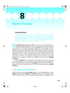
2 But the MOS name specified otherwise, you may assume that the gate is made of heavily doped,highly conductive, polycrystalline silicon, or poly-Si for short. After 2008, the trend is toreintroduce metal gate and replace SiO2 with more advanced dielectrics for the mostadvanced transistors (see section ).The MOS Capacitor is not a widely used device in itself. However, it is part ofthe MOS transistor the topic of the next two chapters. The MOS transistor is by farthe most widely used semiconductor device. An MOS transistor (Fig. 5 2) is an MOScapacitor with two PN junctions flanking the Capacitor . This transistor structure isoften a better structure for studying the MOS Capacitor properties than the MOScapacitor itself as explained in section CONDITION AND FLAT-BAND VOLTAGEIt is common to draw the energy band diagram with the oxide in the middle and thegate and the body on the left- and right-hand sides as shown in Fig.
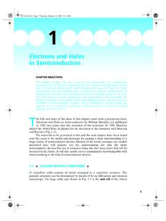
3 5 3. The banddiagram for Vg = 0 (Fig. 5 3b) is quite 5 2An MOS transistor is an MOS Capacitor with PN junctions at two 5 3(a) Polysilicon-gate/oxide/semiconductor Capacitor and (b) its energy banddiagram with no applied +N+ N+polysiliconSiO2(a)(b)P-Silicon bodyEF, eV9 Page 158 Friday, February 13, 2009 2:38 Flat-band Condition and Flat-band Voltage159It is a good strategy to first study the energy band diagram for a special biascondition called the flat-band condition. Flat band is the condition where the energyband (Ec and Ev) of the substrate is flat at the Si SiO2 interface as shown in Fig. 5 condition is achieved by applying a negative voltage to the gate in Fig. 5 3b,thus raising the band diagram on the left-hand side. (See section for the relationbetween voltage and the band diagram.) When the band is flat in the body as inFig. 5 4, the surface electric field in the substrate is zero. Therefore the electric fieldin the oxide is also zero1, , Ec and Ev of SiO2 are flat, too.
4 Ec and Ev of SiO2 areseparated by 9 eV, the Eg of SiO2. E0, the vacuum level, is the energy state ofelectrons outside the material. E0 of SiO2 is above Ec by eV. The differencebetween E0 and Ec is called the electron affinity, another material parameter just asEg is a material parameter. Si has an electron affinity equal to eV. E0 must becontinuous at the Si SiO2 interface as shown in Fig. 5 4 (otherwise the electric fieldwould be infinite). Therefore, Ec of SiO2 is eV higher than Ec of Si. This eV isthe Si SiO2 electron energy barrier. The hole energy barrier is eV in Fig. 5 of these large energy barriers, electrons and holes normally cannot passthrough the SiO2 gate dielectric. Ec in the poly-silicon gate is also lower than the Ecof SiO2 by eV (the Si SiO2 energy barrier). Finally, EF of the N+poly-Si may beassumed to coincide with Ec for simplicity. In SiO2, the exact position of EF has nosignificance.
5 If we place EF anywhere around the middle of the SiO2 band gap,1 According to Gauss s Law, with no interface charge, s s = ox ox where s and ox are the bodysurface field and the oxide 5 4 Energy band diagram of the MOS system at the flat-band condition. A voltageequal to Vfb is applied between the N+-poly-Si gate and the P-silicon body to achieve thiscondition. g is the gate-material work function, and s is the semiconductor work is the vacuum eVxSi eVEc, eVqcs xSi (Ec EF)qcgE0 VfbN Page 159 Friday, February 13, 2009 2:38 PM160 Chapter 5 MOS Capacitorn=Ncexp[(Ec EF)/kT] would be a meaninglessly small number such as 10 60 cm , the position of EF in SiO2 is applied voltage at the flat-band condition, called Vfb, the flat-bandvoltage, is the difference between the Fermi levels at the two terminals.( ) g and s are the gate work function and the semiconductor work function,respectively, in volts.
6 The work function is the difference between E0 and EF. Foran N+-poly-Si gate, g = For the P-Si body, s = V + (Ec EF)/q. Forthe example at hand, Eq. ( ) and Fig. 5 4 indicate a negative Vfb, about ACCUMULATION How would Fig. 5 4 change if a more negative Vg than Vfb is applied? The banddiagram on the gate side would be pushed upward (see section ). The result isshown in Fig. 5 5. Note that Fig. 5 5 is not drawn to scale ( , eV is not aboutthree times the silicon band gap) for the economy of page space. Such not-to-scaledrawings are the norm. When Vg Vfb, s (surface voltage) and Vox (oxide voltage)will be non-zero in general. q s is the band bending in the substrate. Because thesubstrate is the voltage reference, s is negative if Ec bends upward toward thesurface as shown in Fig. 5 5 and positive if Ec bends downward. If this discussion ofthe sign of s sounds strange, please review Sec.
7 Vox is the voltage across theoxide. Again, Vox is negative if the SiO2 energy band tilts up toward the gate as itdoes in Fig. 5 5, and positive if it tilts downward toward the In this case, g happens to be equal to Si. In general, g is defined as the difference between E0 and 5 5 This MOS Capacitor is biased into surface accumulation (ps>p0=Na).(a) Types of charge present. represents holes and represents negative charge. (b) Energyband g s = (a)(b) eVEc, EFEvE0 EcEFEvM O SqVgVoxqfsSiO2 GateP-Si bodyVVg VfbAccumulationcharge, Qacc Page 160 Friday, February 13, 2009 2:38 Surface Depletion161 Because Ev is closer to EF at the surface than in the bulk, the surface holeconcentration, ps, is larger than the bulk hole concentration, p0 = Na. Specifically,( )Since s may be 100 or 200 mV, ps >> Na. That is to say, there are a largenumber of holes at or near the surface. They form an accumulation layer and theseholes are called the accumulation-layer holes, and their charge the accumulationcharge, Qacc.
8 This condition is known as surface accumulation. If the substrate wereN type, the accumulation layer would hold electrons. A relationship that we will use again and again is( )At flat band, Vg = Vfb, s = Vox = 0 and Eq. ( ) is satisfied. If Vg Vfb, thedifference must be picked up by s and Vox. In the case of surface accumulation, smay be ignored in a first-order model since it is quite small and Eq. ( ) becomes ( )Using Gauss s Law,( )where Cox is the oxide capacitance per unit area (F/cm2) and Qacc is theaccumulation charge (C/cm2). Equation ( ) is the usual Capacitor relationship,V= Q/C (or Q = C V) except for the negative sign. In V = Q/C, the capacitorvoltage and charge are both taken from the same electrode. In the MOS capacitortheory, the voltage is the gate voltage, but the charge is the substrate chargebecause interesting things happen in the substrate. This unusual choice leads to thenegative sign in Eq.
9 ( ). Equations ( ) and ( ) tell us( )Therefore, the MOS Capacitor in accumulation behaves like a Capacitor with Q= C V (or C V as explained earlier) but with a shift in V by Vfb. The shift is easilyunderstandable because Qacc = 0 when Vg = Vfb. In general, Eq. ( ) should read( )where Qsub is all the charge that may be present in the substrate, including DEPLETION How would Fig. 5 4 change if a more positive Vg than Vfb is applied? The banddiagram on the gate side will be pulled downward as shown in Fig. 5 6b. Clearly,there is now a depletion region at the surface because EF is far from both Ec and EvpsNaeq skT =VgVfb sVox++=VoxVgVfb = ox Qacc ox------------ =Vox oxTox QaccCox------------ ==QaccCoxVgVfb () =VoxQsub Cox = Page 161 Friday, February 13, 2009 2:38 PM162 Chapter 5 MOS Capacitorand electron and hole densities are both small. This condition is called surfacedepletion. The depletion region has a width, Wdep.
10 Equation ( ) becomes( )( )Qdep is negative because the acceptor ions (after accepting the extra electrons) arenegatively charged. In Eqs. ( ) and ( ), we used [Eq. ( )]. Combining Eqs. ( ), ( ), and ( ),( )This equation can be solved to yield Wdep as a function of Vg. With Wdepdetermined, Vox [Eq. ( )] and s [Eq. ( )] become CONDITION AND THRESHOLD VOLTAGE Let s make Vg in Fig. 5 6 increasingly more positive. This bends the energy banddown further. At some Vg, EF will be close enough to Ec at the Si SiO2 interfacethat the surface is no longer in depletion but at the threshold of inversion. Theterm inversion means that the surface is inverted from P type to N type, orelectron rich. Threshold is often defined as the condition when the surfaceelectron concentration, ns, is equal to the bulk doping concentration, Na. Thatmeans (Ec EF)surface = (EF Ev)bulk, or A = B in Fig. 5 That, in turn, meansFIGURE 5 6 This MOS Capacitor is biased into surface depletion.