Transcription of PN and Metal–Semiconductor Junctions
1 Page 89 Friday, February 13, 2009 5:54 PM. 4. PN and Metal Semiconductor Junctions CHAPTER OBJECTIVES. This chapter introduces several devices that are formed by joining two different materials together. PN junction and metal semiconductor junction are analyzed in the forward- bias and reverse-bias conditions. Of particular importance are the concepts of the depletion region and minority carrier injection. Solar cells and light-emitting diode are presented in some detail because of their rising importance for renewable energy generation and for energy conservation through solid-state lighting, respectively. The metal semiconductor junction can be a rectifying junction or an ohmic contact. The latter is of growing importance to the design of high-performance transistors.
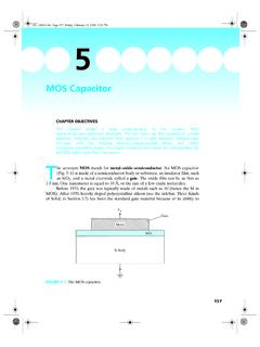
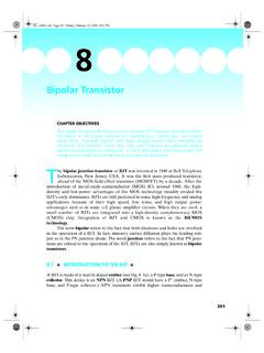
2 PART I: PN JUNCTION. As illustrated in Fig. 4 1, a PN junction can be fabricated by implanting or diffusing (see Section ) donors into a P-type substrate such that a layer of semiconductor is converted into N type. Converting a layer of an N-type semiconductor into P type with acceptors would also create a PN junction. A PN junction has rectifying current voltage (I V or IV) characteristics as shown in Fig. 4 2. As a device, it is called a rectifier or a diode. The PN junction is the basic structure of solar cell, light-emitting diode, and diode laser, and is present in all types of transistors. In addition, PN junction is a vehicle for studying the theory Donor ions N type P type FIGURE 4 1 A PN junction can be fabricated by converting a layer of P-type semiconductor into N-type with donor implantation or diffusion.
3 89. Page 90 Friday, February 13, 2009 5:54 PM. 90 Chapter 4 PN and Metal Semiconductor Junctions I . V. I. N P. V. Reverse bias Forward bias Diode symbol FIGURE 4 2 The rectifying IV characteristics of a PN junction. of the depletion layer, the quasi-equilibrium boundary condition, the continuity equation, and other tools and concepts that are important to the understanding of transistors. BUILDING BLOCKS OF THE PN JUNCTION THEORY . For simplicity, it is usually assumed that the P and N layers are uniformly doped at acceptor density Na, and donor density Nd, This idealized PN junction is known as a step junction or an abrupt junction. Energy Band Diagram and Depletion Layer of a PN Junction Let us construct a rough energy band diagram for a PN junction at equilibrium or zero bias voltage.
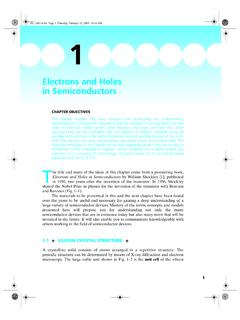
4 We first draw a horizontal line for EF in Fig. 4 3a because there is only one Fermi level at equilibrium (see Sec. ). Figure 4 3b shows that far from the junction, we simply have an N-type semiconductor on one side (with Ec close to EF), and a P-type semiconductor on the other side (with Ev close to EF). Finally, in Fig. 4 3c we draw an arbitrary (for now) smooth curve to link the Ec from the N layer to the P layer. Ev of course follows Ec, being below Ec by a constant Eg. QUESTION Can you tell which region (P or N) in Fig. 4 3 is more heavily doped? (If you need a review, see Section ). Figure 4 3d shows that a PN junction can be divided into three layers: the neutral N layer, the neutral P layer, and a depletion layer in the middle.
5 In the middle layer, EF is close to neither Ev nor Ec. Therefore, both the electron and hole concentrations are quite small. For mathematical simplicity, it is assumed that n 0 and p 0 in the depletion layer ( ). The term depletion layer means that the layer is depleted of electrons and holes. 1 N and N are usually understood to represent the compensated (see end of Section ), or the net, d a dopant densities. For example, in the N-type layer, there may be significant donor and acceptor concen- trations, and Nd is the former minus the latter. Page 91 Friday, February 13, 2009 5:54 PM. Building Blocks of the PN Junction Theory 91. N region P region EF. (a). Ec Ec EF. Ev Ev (b). Ec EF. Ev (c). Neutral Depletion Neutral N region layer P region Ec EF.
6 Ev (d). FIGURE 4 3 (a) and (b) Intermediate steps of constructing the energy band diagram of a PN junction. (c) and (d) The complete band diagram. Built-In Potential Let us examine the band diagram of a PN junction in Fig. 4 4 in greater detail. Figure 4 4b shows that Ec and Ev are not flat. This indicates the presence of a voltage differential. The voltage differential, bi, is called the built-in potential. A built-in potential is present at the interface of any two dissimilar materials. We are usually Page 92 Friday, February 13, 2009 5:54 PM. 92 Chapter 4 PN and Metal Semiconductor Junctions N type P type Nd Na (a). Ec qfbi qB. EF. qA Ev (b). V. fbi x xN 0 xP. (c). FIGURE 4 4 (a) A PN junction.
7 The built-in potential in the energy band diagram (b) shows up as an upside down mirror image in the potential plot (c). unaware of them because they are difficult to detect directly. For example, if one tries to measure the built-in potential, bi, by connecting the PN junction to a voltmeter, no voltage will be registered because the net sum of the built-in potentials at the PN. junction, the semiconductor metal contacts, the metal to wire contacts, etc., in any closed loop is zero (see the sidebar, Hot-Point Probe, Thermoelectric Generator and Cooler, in Sec. ). However, the built-in voltage and field are as real as the voltage and field that one may apply by connecting a battery to a bar of semiconductor.
8 For example, electrons and holes are accelerated by the built-in electric field exactly as was discussed in Chapter 2. Applying Eq. ( ) to the N and P regions, one obtains qA kT N. N-region n = Nd = Nce A = kT. ------- ln -----c- q Nd 2. n qB kT NcNa P-region n = -----i- = N c e B = kT. ------- ln ------------ 2. - Na q ni kT N c N a N . - ln -----c- . bi = B A = ------- ln ------------ 2. q n N d . i Page 93 Friday, February 13, 2009 5:54 PM. Building Blocks of the PN Junction Theory 93. kT N d N a bi = ------- ln ------------ - ( ). q 2. n i The built-in potential is determined by Na and Nd through Eq. ( ). The larger the Na or Nd is, the larger the bi is. Typically, bi is about V for a silicon PN junction.
9 Since a lower Ec means a higher voltage (see Section ), the N side is at a higher voltage or electrical potential than the P side. This is illustrated in Fig. 4 4c, which arbitrarily picks the neutral P region as the voltage reference. In the next section, we will derive V(x) and Ec(x). Poisson's Equation Poisson's equation is useful for finding the electric potential distribution when the charge density is known. In case you are not familiar with the equation, it will be derived from Gauss's Law here. Applying Gauss's Law to the volume shown in Fig. 4 5, we obtain s ( x + x ) A s ( x ) A = xA ( ). where s is the semiconductor permittivity and, for silicon, is equal to 12 times the permittivity of free space.
10 Is the charge density (C/cm3) and is the electric field. (x + x) (x) . ---------------------------------------- ---- = ---- ( ). x s A. a re A. (x) (x x). r x x FIGURE 4 5 A small volume in a semiconductor, used to derive the Poisson's equation. Page 94 Friday, February 13, 2009 5:54 PM. 94 Chapter 4 PN and Metal Semiconductor Junctions Taking the limit of x 0, d . ------- = ---- ( ). dx s d 2V. - = d . --------- - ------- = --- ( ). dx 2 dx s Equation ( ) or its equivalent, Eq. ( ), is Poisson's equation. It will be the starting point of the next section. DEPLETION-LAYER MODEL . We will now solve Eq. ( ) for the step junction shown in Fig. 4 6. Let's divide the PN junction into three regions the neutral regions at x > xP and x < xN, and the depletion layer or depletion region in between, where p = n = 0 as shown in Fig.