Transcription of PCA82C250 CAN controller interface - NXP
1 1. General descriptionThe PCA82C250 is the interface between a CAN protocol controller and the physical bus. The device provides differential transmit capability to the bus and differential receive capability to the CAN Features and benefits Fully compatible with the ISO 11898 standard High speed (up to 1 MBd) Bus lines protected against transients in an automotive environment Slope control to reduce Radio Frequency Interference (RFI) Differential receiver with wide common-mode range for high immunity against ElectroMagnetic Interference (EMI) Thermally protected Short-circuit proof to battery and ground Low-current Standby mode An unpowered node does not disturb the bus lines At least 110 nodes can be connected3. Applications High-speed automotive applications (up to 1 MBd).4. Quick reference data PCA82C250 CAN controller interfaceRev. 06 25 August 2011 Product data sheetTable reference dataSymbolParameterConditionsMinMaxUnitV CCsupply currentStandby mode-170 A1/tbitmaximum transmission speednon-return-to-zero1-MBdVCANCANH, CANL input/output voltage 8+18 VVdiffdifferential bus delayHigh-speed mode-50nsTambambient temperature 40+125 CPCA89C250 All information provided in this document is subject to legal disclaimers.
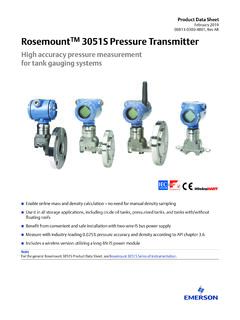
2 NXP 2011. All rights data sheetRev. 06 25 August 2011 2 of 18 NXP SemiconductorsPCA82C250 CAN controller interface5. Ordering information 6. Block diagram 7. Pinning Pinning Table informationType numberPackageNameDescriptionVersionPCA82 C250 TSO8plastic small outline package; 8 leads; body width mmSOT96-1 Fig diagrammka669 RECEIVERHSREFERENCEVOLTAGESLOPE/STANDBYP ROTECTIONDRIVER32548167 GNDCANLCANHVrefTXDRsRXDVCCPCA82C250 Fig configuration12348765mka670 PCA82C250 RsCANHGNDCANLVrefRXDVCCTXDPCA89C250 All information provided in this document is subject to legal disclaimers. NXP 2011. All rights data sheetRev. 06 25 August 2011 3 of 18 NXP SemiconductorsPCA82C250 CAN controller Pin description 8. Functional descriptionThe PCA82C250 is the interface between a CAN protocol controller and the physical bus. It is primarily intended for high-speed automotive applications (up to 1 MBd). The device provides differential transmit capability to the bus and differential receive capability to the CAN controller .
3 It is fully compatible with the ISO 11898 current limiting circuit protects the transmitter output stage against short-circuit to positive and negative battery voltage. Although the power dissipation is increased during this fault condition, this feature will prevent destruction of the transmitter output the junction temperature exceeds a value of approximately 160 C, the limiting current of both transmitter outputs is decreased. Because the transmitter is responsible for the major part of the power dissipation, this will result in reduced power dissipation and hence a lower chip temperature. All other parts of the PCA82C250 will remain in operation. The thermal protection is needed, in particular, when a bus line is CANH and CANL lines are also protected against electrical transients which may occur in an automotive 8 (Rs) allows three different modes of operation to be selected: High-speed, Slope control and high-speed operation, the transmitter output transistors are simply switched on and off as fast as possible.
4 In this mode, no measures are taken to limit the rise and fall slope. Use of a shielded cable is recommended to avoid RFI problems. The High-speed mode is selected by connecting pin 8 to lower speeds or shorter bus length, an unshielded twisted pair or a parallel pair of wires can be used for the bus. To reduce RFI, the rise and fall slope should be limited. The rise and fall slope can be programmed with a resistor connected from pin 8 to ground. The slope is proportional to the current output at pin a HIGH level is applied to pin 8, the circuit enters a low-current Standby mode. In this mode, the transmitter is switched off and the receiver is switched to a low current. If dominant bits are detected (differential bus voltage > V), RXD will be switched to a Table descriptionSymbolPinDescriptionTXD1trans mit data inputGND2groundVCC3supply voltageRXD4receive data outputVref5reference voltage outputCANL6 LOW-level CAN voltage input/outputCANH7 HIGH-level CAN voltage input/outputRs8slope resistor inputPCA89C250 All information provided in this document is subject to legal disclaimers.
5 NXP 2011. All rights data sheetRev. 06 25 August 2011 4 of 18 NXP SemiconductorsPCA82C250 CAN controller interfaceLOW level. The microcontroller should react to this condition by switching the transceiver back to normal operation (via pin 8). Because the receiver is slow in Standby mode, the first message will be lost. [1]X = don t care. 9. Limiting values [1]In accordance with IEC 60747-1 . An alternative definition of virtual junction temperature is: Tvj=Tamb+Pd Rth(vj-a), where Rth(j-a) is a fixed value to be used for the calculation of Tvj. The rating for Tvj limits the allowable combinations of power dissipation (Pd) and ambient temperature (Tamb).[2]Classification A: human body model; C = 100 pF; R = 1 500 ; V = 2 000 V.[3]Classification B: machine model; C = 200 pF; R = 25 ; V = 200 table of the CAN transceiverSupplyTXDCANHCANLBus V to V to V1 (or floating) floatingfloatingrecessive1< 2 V (not powered)X[1]floatingfloatingrecessiveX[1]2V<VCC< V> [1]2V<VCC< [1]floating if VRs> if VRs> [1]Table Rs summaryCondition forced at pin RsModeResulting voltage or current at pin RsVRs> < 10 A 10 A<IRs< 200 ASlope <VRs< < < 500 ATable valuesIn accordance with the Absolute Maximum Rating System (IEC 60134).
6 All voltages are referenced to pin 2; positive input voltage + voltage at pins 1, 4, 5 and 8 + VV6, 7DC voltage at pins 6 and 70 V < VCC< ; no time limit + voltage at pins 6 and 7see Figure 8 150+100 VTstgstorage temperature 55+150 CTambambient temperature 40+125 CTvjvirtual junction temperature[1] 40+150 CVesdelectrostatic discharge voltage[2] 2000+2 000V[3] 200+200 VPCA89C250 All information provided in this document is subject to legal disclaimers. NXP 2011. All rights data sheetRev. 06 25 August 2011 5 of 18 NXP SemiconductorsPCA82C250 CAN controller interface10. Thermal characteristics 11. Characteristics Table characteristicsSymbolParameterConditionsTypUnitRth(j-a)thermal resistance from junction to ambientin free air160K/WTable to V; Tamb= 40 to +125 C; RL=60 ; I8> 10 A; unless otherwise specified; all voltages referenced to ground (pin 2); positive input current; all parameters are guaranteed over the ambient temperature range by design, but only 100 % tested at +25 currentdominant; V1=1V--70mArecessive; V1=4V; R8=47k --14mArecessive; V1=4V; V8=1V--18mAStandby; Tamb<90 C[1]-100170 ADC bus transmitterVIHHIGH-level input voltageoutput + VVILLOW-level input voltageoutput dominant input currentV1=4V 200-+30 AIILLOW-level input currentV1=1V 100- 600 AV6,7recessive bus voltageV1= 4 V; no output leakage current 2V<(V6,V7)<7V 2-+1 mA 5V<(V6,V7)<18V 5-+12mAV7 CANH output voltageV1= output voltageV1= 1 V6, 7difference between output voltage at pins 6 and 7V1= 1 ; RL=45 ; VCC 4 V; no load 500-+50mVIsc7short-circuit CANH currentV7= 5V.
7 VCC 5V-- 105mAV7= 5V; VCC= 120mAIsc6short-circuit CANL currentV6= 18 V--160mADC bus receiver: V1= 4 V; pins 6 and 7 externally driven; 2V<(V6,V7) < 7 V; unless otherwise specifiedVdiff(r)differential input voltage (recessive) + 7V<(V6,V7)<12V; not Standby mode + (d)differential input voltage (dominant) 7V<(V6,V7)<12V; not Standby (hys)differential input hysteresissee Figure 5-150- mVVOHHIGH-level output voltagepin 4; I4= 100 information provided in this document is subject to legal disclaimers. NXP 2011. All rights data sheetRev. 06 25 August 2011 6 of 18 NXP SemiconductorsPCA82C250 CAN controller interface [1]I1=I4=I5=0mA; 0V<V6<VCC; 0 V < V7<VCC; V8= output voltagepin 4; I4= 1 resistanceCANH, CANL5-25k Rdiffdifferential input resistance20-100k Ciinput capacitanceCANH, CANL--20pFCdiffdifferential input capacitance--10pFReference outputVrefreference output voltageV8=1V; 50 A<I5<50 ; 5 A<I5<5 (CL= 100 pF; see Figure 3, Figure 4, Figure 6 and Figure 7)tbitminimum bit timeRext=0 --1 stonTXDdelay TXD to bus activeRext=0 --50nstoffTXDdelay TXD to bus inactiveRext=0 -4080nstonRXDdelay TXD to receiver activeRext=0 -55120nstoffRXDdelay TXD to receiver inactiveRext=0 ; VCC< ; Tamb<+85 C-82150nsRext=0 ; VCC< ; Tamb<+125 C-82170nsRext=0 ; VCC< ; Tamb<+85 C-90170nsRext=0 ; VCC<.
8 Tamb<+125 C-90190nstonRXDdelay TXD to receiver activeRext=47k -390520nsRext=24k -260320nstoffRXDdelay TXD to receiver inactiveRext=47k -260450nsRext=24k -210320ns SR differential output voltage slew rateRext=47k -14- V/ stWAKE wake-up time from Standbyvia pin 8--20 stdRXDLbus dominant to RXD LOWV8= 4 V; Standby mode--3 sStandby/Slope Control (pin 8)V8input voltage for current for high-speedV8=0V-- 500 AVstbinput voltage for Standby control mode current 10- 200 AVslopeslope control mode ..continuedVCC= to V; Tamb= 40 to +125 C; RL=60 ; I8> 10 A; unless otherwise specified; all voltages referenced to ground (pin 2); positive input current; all parameters are guaranteed over the ambient temperature range by design, but only 100 % tested at +25 information provided in this document is subject to legal disclaimers. NXP 2011. All rights data sheetRev. 06 25 August 2011 7 of 18 NXP SemiconductorsPCA82C250 CAN controller interface Fig circuit for dynamic diagram for dynamic pF100 pF60 100 nF+5 VVdiffPCA89C250 All information provided in this document is subject to legal disclaimers.
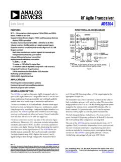
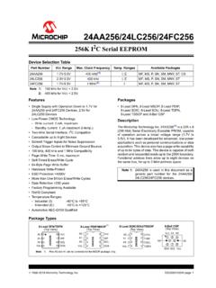
9 NXP 2011. All rights data sheetRev. 06 25 August 2011 8 of 18 NXP SemiconductorsPCA82C250 CAN controller interface V1= diagram for wake-up from Standby. V1=4V; V8= diagram for bus dominant to RXD waveforms of the applied transients shall be in accordance with ISO 7637 part 1 , test pulses 1, 2, 3a and circuit for automotive V0 VVdiffVRXD015aaa246 PCA82C250 RXDVrefTXDCANHCANLGNDVCCSCHAFFNERGENERAT OR60 +5 VRextRs1 nF1 nFPCA89C250 All information provided in this document is subject to legal disclaimers. NXP 2011. All rights data sheetRev. 06 25 August 2011 9 of 18 NXP SemiconductorsPCA82C250 CAN controller interface12. Application information Fig of the CAN 10. Application with galvanic ,YTXDRXDVrefCANLCAN BUSLINECANHRsRext+5 V100 nF124 124 VCCGNDVDDVSSRext+5 V+5 V+5 V0 V100 nF100 nF390 390 390 k k 390 6N1376N137mka678 PCA82C250 CAN-TRANSCEIVERTXDRXDVrefCANLCAN BUS LINECANHRs+5 V100 nF124 124 VCCGNDSJA1000 CAN-CONTROLLERTX0TX1RX0RX1 PCA89C250 All information provided in this document is subject to legal disclaimers.
10 NXP 2011. All rights data sheetRev. 06 25 August 2011 10 of 18 NXP SemiconductorsPCA82C250 CAN controller interface Fig 11. Internal pin information provided in this document is subject to legal disclaimers. NXP 2011. All rights data sheetRev. 06 25 August 2011 11 of 18 NXP SemiconductorsPCA82C250 CAN controller interface13. Package outline Fig 12. Package outline SOT96-1 (SO8) (1)E(2)(1)eHELLpQZywv REFERENCESOUTLINEVERSIONEUROPEANPROJECTI ONISSUE DATE IEC JEDEC (inch dimensions are derived from the original mm dimensions)Notes1. Plastic or metal protrusions of mm ( inch) maximum per side are not Plastic or metal protrusions of mm ( inch) maximum per side are not included. SOT96-1 XwM AA1A2bpDHELpQdetail XEZecLvMA(A )3A45pin 1 index18y076E03 mmscaleSO8: plastic small outline package; 8 leads; body width mmSOT96-199-12-2703-02-18 PCA89C250 All information provided in this document is subject to legal disclaimers. NXP 2011. All rights data sheetRev.