Transcription of Simulating Verilog RTL using Synopsys VCS
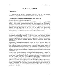
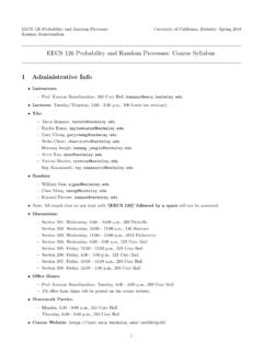
1 Simulating Verilog RTL using Synopsys VCSCS250 Tutorial 4 (Version 091209a)September 12, 2010 Yunsup LeeIn this tutorial you will gain experience using Synopsys VCS to compile cycle-accurate executablesimulators from Verilog RTL. You will also learn how to use the Synopsys Waveform viewer totrace the various signals in your design. Figure 1 illustrates the basic VCS toolflow and RISC-Vtoolchain. For more information about the RISC-V toolchain consultTutorial 3: Build, Run, andWrite RISC-V takes a set of Verilog files as input and produces a simulator. When you execute the simulatoryou need some way to observe your design so that you can measure its performance and verify that itis working correctly.
2 There are two primary ways to observe your design: (1) you can use$displaystatements in your Verilog RTL to output textual trace information, or (2) you can instruct thesimulator to automatically write transition information about each signal in your design to a is standard text format for this type of signal transition trace information called the ValueChange Dump format (VCD). Unfortunately, these textual trace files can become very large veryquickly, so Synopsys uses a proprietary compressed binary trace format called VCD Plus (VPD).You can view VPD files using the Synopsys waveform viewer called Discovery Visual Environment(DVE).
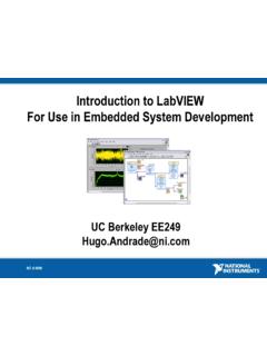
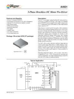
3 VerilogSource(RTL)VCSRTLSimExecute SIMVPDTestOutputsDVE GUIASMS ourceCodeRISC-VBinaryRISC-V toolchainCSourceCodeVerilogLibrary(RTL)F igure 1: VCS Toolflow and RISC-V Assembler ToolchainCS250 Tutorial 4 (Version 091209a), Fall 20102 You will be using a simple unpipelined RISC-V v1 processor as your design example for this tutorial,and thus you will also learn how to build and run test codes on the processor simulator. Figure 2shows the block diagram for the example processor. Figure 1 shows the RISC-V toolchain whichstarts with an RISC-V assembly file and generates a binary file suitable to run on the cycle-accuratesimulator. This tutorial assumes you are familiar with the RISC-V ISA.
4 For more information pleaseconsult theRISC-V Processor Specification.+4 Instruction MemRegFileSignExtendDecoder>>1 CmpData Memir[24:20]branchpc+4pc_selrd0rd1 AddControlSignalseq?wb_selRegFileir[24:2 0]rf_wenvalrwPCtohosttestrig_tohosttohos t_envalop0op1addrwdatardatair[19:15]ir[1 1:0]Figure 2: Block diagram for Unpipelined RISC-V v1 ProcessorThe following documentation is located in the course locker~cs250/manualsand provides addi-tional information about VCS, DVE, and Verilog . VCS User Guide VCS Quick Reference Discovery Visual Environment User Guide Unified Command Line Interface User Guide Language specification for the original Verilog -1995 Language specification for Verilog -2001 Language specification for Verilog -2005 Standard for Verilog Register TransferLevel Synthesis Language specification for the original SystemVerilog-2005 Language specification for SystemVerilog-2009CS250 Tutorial 4 (Version 091209a), Fall 20103 Getting startedYou can follow along through the tutorial yourself by typing in the commands marked with a % symbol at the shell prompt.
5 To cut and paste commands from this tutorial into your bash shell(and make sure bash ignores the % character) just use an alias to undefine the % characterlike this:% alias %=""All of the CS250 tutorials should be ran on an EECS Instructional machine. Please see the coursewebsite for more information on the computing resources available for CS250 students. Once youhave logged into an EECS Instructional you will need to setup the CS250 toolflow with the source ~cs250/ this tutorial you will be using an unpipelined RISC-V v1 processor as your example RTL a working directory and copy files from the course locker using the following mkdir tut4% cd tut4% TUTROOT=$PWD% cp -R ~cs250/examples/v-riscv-v1-1stage/* $TUTROOTB efore starting, take a look at the subdirectories in the project directory.
6 All of your projects willhave a similar structure. Source RTL should be placed in thesrcdirectory and test input filesshould be placed in theriscv-testsdirectory. Thebuilddirectory will contain all generatedcontent including simulators, synthesized gate-level Verilog , and final layout. In this course youwill always try to keep generated content separate from your source RTL. This keeps your projectdirectories well organized, and helps prevent you from unintentionally modifying your source are subdirectories in thebuilddirectory for each major step in the CS250 toolflow. Thesesubdirectories will contain scripts and configuration files necessary for running the tools requiredfor that step in the toolflow.
7 For example, thebuild/vcs-sim-rtldirectory contains a makefilewhich can build Verilog simulators and run tests on these simulators. For more information, pleaseconsultTutorial 2: Bits and Pieces of CS250 s toolflow. You should browse the source code for theprocessor insrcto become familiar with the design. Thecsrcdirectory contains Direct C sourcefiles. These C source files are used in the Verilog test harness to simulate memory, parse and loadELF files. Direct C is a very convenient way to glue Verilog simulation with C functions, whichwill be used through out the course. Please refer to the VCS user guide chapter 19 (C LanguageInterface) for more information on Direct the SimulatorIn this section you will first see how to run VCS from the command line, and then you will see howto automate the process using a makefile.
8 To build the simulator you need to run thevcscompilerwith the appropriate command line arguments and a list of input Verilog Tutorial 4 (Version 091209a), Fall 20104% cd $TUTROOT/build/vcs-sim-rtl% vcs -full64 -PP +lint=all,noVCDE +v2k -timescale=1ns/10ps \+vc+list -CC "-I$VCS_HOME/include" \+define+CLOCK_PERIOD= \+define+IMEM_DELAY= \+define+DMEM_DELAY= \../../ \../../ \../../ \../../ \../../ \../../ \../../ \../../ \../../ \../../ \../../ \By default, VCS generates a simulator namedsimv. The-full64command line argument makesyou use the 64-bit line argument turns on support for using theVPDtraceoutput format. The+lint=all,noVCDE argument turns on Verilog warnings except the VCDE warning.
9 Since it is relatively easy to write legal Verilog code which is probably functionallyincorrect, you will always want to use this argument. For example, VCS will warn you if youconnect nets with different bitwidths or forget to wire up a port. Always try to eliminate all VCScompilation errorsandwarnings. Since you will be making use of various Verilog -2001 languagefeatures, you need to set the+v2kcommand line option so that VCS will correctly handle thesenew constructs. Verilog allows a designer to specify how the abstract delay units in their designmap into real time units using the timescalecompiler directive.
10 To make it easy to change thisparameter you will specify it on the command line instead of in the Verilog source.+vc+list -CC"-I$VCSHOME/include"arguments let you compile Direct C. After these arguments you list theVerilog source files and Direct C source files. After running this command, you should see textoutput indicating that VCS is parsing the Verilog files and compiling the modules. Notice thatVCS actually generates ANSI C code which is then compiled usinggcc. When VCS is finished youshould see asimvexecutable in the build in all the Verilog source files on the command line can be very tedious, so you will usemakefiles to help automate the process of building your simulators.