Transcription of Soldering Guidelines for Mounting Bottom-terminated …
1 Soldering Guidelines for Mounting Bottom-terminated ComponentsApplication Note 62 2016, Peregrine Semiconductor Corporation. All rights reserved. Headquarters: 9380 Carroll Park Drive, San Diego, CA, 92121 Application NoteDOC-78164-1 (10/2016) objective of this application note is to provide Peregrine Semiconductor customers with general Guidelines for Soldering and assembly of quad flat pack no leads (QFNs) and other Bottom-terminated components (BTCs). Precise process development and designed experi-mentation are needed to optimize specific are thermally enhanced plastic leadless packages with electrical connections made via lands on the bottom side of the component to the surface of the connecting substrate (PCB, ceramic, LTCC, etc.). Reflow Soldering of surface mount assemblies provides mechanical, thermal and electrical connections between the component leads or terminations and the substrate surface mount land pattern.
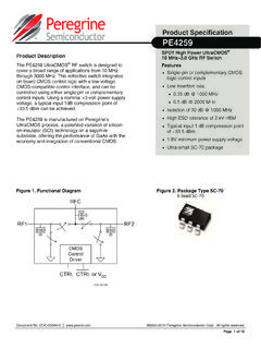
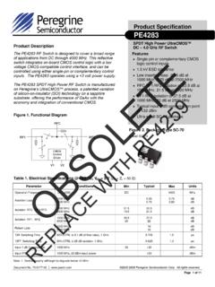
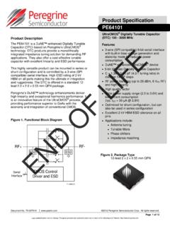
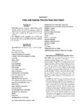
2 Solder paste may be applied to the surface mount lands by various methods, such as screen printing and stencil printing. Peregrine Semicon-ductor packages are categorized as surface mount components (SMCs). Unlike through-hole components, SMCs rely entirely upon the solder interface for mechanical strength. The solder joint properties, design and reflow process are of critical importance for successful assembly. Figure 1 shows the top side and bottom side of the QFN 1 QFN Top Side and Bottom SideTop SideBottom SideApplication Note 62 Soldering Guidelines for BTCsPage 2 DOC-78164-1 (10/2016) Board Land Pattern Please refer to the Peregrine datasheet for the recommended land pattern for the package terminal pads and the center slug. Figure 2 shows an example of a QFN land pattern. Users have the option to either use solder mask defined (SMD) pads or non-solder mask defined (NMSD) pads.
3 High temperature FR-4 or BT laminate (glass transition temperature Tg = +170 C to +185 C) is generally recommended for lead-free QFN assembly. The peak lead-free reflow temperatures range from +245 C to +260 C using a lead-free alloy such as SAC 305 ( ). The QFN package is also solderable with eutectic (tin/lead solder paste Sn63Pb37 alloy) at a peak reflow temperature of +225 C to +230 C. Please follow board design requirements based in IPC A-600 Acceptability of Printed Circuit Boards(1) and IPC 6012D Qualification and Performance of Rigid Printed Boards(2). PCB Surface Finish Electroless nickel/electroless palladium/immersion gold (ENEPIG) is the preferred surface finish for the PCB copper land and pads. Electroless nickel/immersion gold (ENIG), organic solderability preservative (OSP) coating over copper land pads if used for cost tradeoffs should be carefully evaluated for solder joint reliability post reflow prior to manufacturing release.
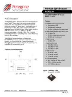
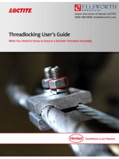
4 In general, NSMD pads are preferred over SMD pads for all LGA packages. However, selection of NSMD versus SMD should be based on complexity of the board design and board suppliers capability for solder mask registration and tolerance. Solder mask is recommended between all pads. The NSMD pads are illustrated in Figure 3 and the SMD pads are illustrated in Figure 2 QFN Land PatternFigure 3 NSMD Pads(solder mask away from copper)Application Note 62 Soldering Guidelines for BTCsDOC-78164-1 (10/2016)Page PSolder Paste Printing Solder PasteThe solder paste is the vehicle that provides the flux and solder alloy necessary for a reliable and consistent assembly process. A low residue, no-clean solder paste (eutectic Sn63/Pb37 or lead-free SAC305/405 alloy SnAgCu) is commonly used. A water-soluble paste can be used if the residue can be adequately cleaned from underneath the package.
5 Typically, the choice of solder paste determines the profile and reflow parameters. Most solder paste manufacturers provide a suggested thermal profile for their products and must be referenced prior to manufacturing. This thermal profile should also be used to meet the moisture sensi-tivity level (MSL) Guidelines for the package per IPC/JEDEC J-STD 020E Moisture/Reflow Sensitivity Classification for Non-hermetic Solid State Surface Mount Devices(3).Solder paste is typically composed of three major constituents: solder alloy powder, vehicle system and flux system. The vehicle system primarily acts as a carrier for the alloy powder, a compatible matrix for the flux system and a basis for desirable rheology. The flux cleans the alloy powder and the substrates to be joined, and facilitates wetting and formation of the solder joint. The flux is classified based on its activity level and chemical nature, namely rosin-based (RMA), water-soluble or no-clean.
6 Water-soluble flux is designed so that its residue after Soldering can be removed using pure water or water with saponifier or an additive. No-clean solder paste is designed to not require cleaning after it is reflowed. The amount of residue left behind is often designed to not interfere with bed of nails/pin tests (shorts/open electrical test) and is non-tacky. Please refer to Surface Mount Technology: Principles and Practices(4). Lead-free SoldersThe European Union RoHS/REACH environmental directives have required an industry-wide conversion from lead-based solders to lead-free. Lead-based solders are now being replaced by lead-free solders for both package and second-level assembly. The most common replacements for 63Sn37Pb (eutectic melt temperature +183 C) are (SAC305) and (SAC405) solders, which have a eutectic point of +217 C. Due to the non-uniformity of heat distribution on boards during reflow, the SAC solders reflow profile contains a peak temperature of +250 C.
7 The peak can be as high as +260 C depending on the assembler s equipment and process capability. The high peak tempera-tures can cause a multitude of problems such as delamination at interfaces, external cracking, solder extrusion, etc. An optimized reflow profile and controlled ramp and cool down Figure 4 SMD Pads(solder mask encroaching on copper)Application Note 62 Soldering Guidelines for BTCsPage 4 DOC-78164-1 (10/2016) essential for reliable assemblies . Please refer to Surface Mount Technology: Principles and Practices(4).Solder StencilsThe formation of consistent solder joints is a requirement for good assembly yields. The contrast between a large exposed pad and the small lead fingers of the QFN package can present a challenge in producing an even standoff height, so careful consideration should be given to an optimized stencil stencil thickness, as well as the stencil opening geometry, determines the precise volume of solder paste deposited onto the device land pattern.
8 Stencil alignment accuracy and consistent solder volume transfer are critical for uniform reflow are usually made of nickel buildup or stainless steel. The nickel buildup stencil offers smoother side walls over a laser cut stainless steel stencil. Apertures are typically trape-zoidal, which helps to ensure uniform release of solder paste and reduce smearing as shown in Figure 5. Thickness of stencils used in manufacturing varies from mm to mm ( inch to inch) in range, with a typical mm ( inch) stencil design for mm pitch components. The actual thickness of the stencil is dependent on other surface mount devices on the PCB, in addition to the area and aspect ratio of the minimum aperture squeegee with a durometer of 95 or harder (such as stainless steel) is typically used to transfer the paste from the stencil to the board land pattern. The blade angle and speed must be fine-tuned to ensure even solder paste transfer.
9 An inspection of the printed solder paste is recommended before parts placement. A repeatable brick-shaped solder deposit is the most important factor for robust reflow yields. Please refer to IPC-7525 Stencil Design Guidelines (5).Figure 5 Solder Stencil Profile (Side View)StencilPCBS tencil apertures should be tapered to produce more uniform release of solder Note 62 Soldering Guidelines for BTCsDOC-78164-1 (10/2016)Page Pad Stencil DesignThe stencil aperture for the terminal fingers is typically designed to match the PCB/substrate pad size 1:1. For fine pitch components of mm pitch and below, it may be necessary to reduce the stencil aperture by 20% to prevent shorting beneath the QFN. Please refer to the aspect ratio and area ratio requirements outlined in IPC-7525 Stencil Design Guidelines (5) for adequate print volume and board area ratio of the stencil is critical for the printing to get good paste release.
10 For very small apertures where the area ratio is less than mm, the stencil must be nickel formed. This type of stencil has better release characteristics over stencils that are laser etched. Please check with your stencil manufacturer for recommendations when designing an aperture with unique Ratio = Width of Aperture Opening/Stencil Foil Thickness = W/TArea Ratio = Area of Aperture Opening/Area of Aperture Walls = W L / 2 (L+W) TThe aspect ratio relates to the manufacture of stencils. Stencil manufacturers require the aspect ratio to be > (see IPC-7525 Stencil Design Guidelines (5)). The higher the area ratio the better the solder paste release, in addition to depositing more volume. Stencil thickness is inversely proportional to the area ratio. The thinner the stencil the higher the area ratio will be, resulting in a robust solder paste Pad Stencil DesignThe QFN package is thermally and electrically efficient due to the exposed die attach pad on the underside of the package.