Transcription of Totem-pole PFC reference design with SiC technology
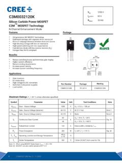
1 Totem-pole PFC reference design with SiCtechnologySTMicroelectronicsSTMicroel ectronics powers totem pole PFC with SiCMOSFETs, thyristor SCRs and digital controlBridgeless Totem-pole PFCI nrush current limiter with SCRs in Totem-pole PFC kW totem pole PFC solution with SCR Inrush current limiterKey Power Product FamiliesBridgeless Totem-pole PFCS upporting Car Electrification and Power ConversionIncreased power density with totem pole boostSmart Inrush Current LimitationSCR high reliability without moving partsBasic single phase PFC topologies for CCMB ridgelessWith input bridge rectifierSimple BoostTotem-pole+Simple+Simple input voltage sensing-Two diodes in series all the time+Higher efficiency-Input voltage sensing requires OpAmp-More complex -Needs SiCMOSFETs with no QRRof diode 400V400 VSiCSiCSiCSiBasic single phase PFC topologies for CCMB
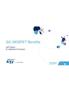
2 RidgelessWith input bridge rectifierSimple BoostTotem-polejunctions in series:3junctions in series:2400V400 VSiCSiCSiCSiS2 off, inductor current fallingTotem pole bridgeless PFC working in CCMtotem pole PFC operation in steady-stateLAODS2 VACIACVDCSCR1 SCR2S1 LAODS2 VACIACVDCSCR1 SCR2S1 LAODS2 VACIACVDCSCR1 SCR2S1 LAODS2 VACIACVDCSCR1 SCR2S1S1 on, inductor current risingS2 off, inductor current risingS1 off, inductor current fallingVAC> 0S1controls PFC choke chargingS2body diode is used only for discharging choke to the outputS2can be switched on during toffto reduce voltage drop of the body diodeVAC< 0S2controls PFC choke chargingS1body diode is used only for discharging choke to the outputS1can be switched on during toffto reduce voltage drop of the body diodeInrush current limiter with SCRs in Totem-pole PFC Smart and Reliable control of the AC Power Delivery Smooth Progression but Fast Power UpRobust against surges, Immune to electrical transientsNo contact bouncing.
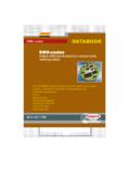
3 No EMI noiseInrush current limiter with SCRs in Totem-pole PFCGDL400 VDCN1200V600V600V1200 VLN600V600 VNTCR elayGDGDGD1200V1200V400 VDCICL with NTC and bypassing relayICL with SCRs Diodes are used for returning current path Resistive element is inserted into current path (NTC or PTC) NTC is bypassed after startup by relay to decrease power losses on NTC SCRs are used for returning current path When SCR are not being switched, output capacitor is disconnected During startup phase, pulses to SCR are being time controlled to slowly charge output capacitor This method requires timing MCU requiredIAC_RMS = 6 AIAC(10 A/div)VACVDCI nrush current limiter with SCRs in Totem-pole PFCVDCVACIAC_RMS= 6 AIAC(10 A/div)ICL with NTC and bypassing relayICL with SCRs+Relay can be driven by simple delaying circuit-Relay causes audible noise when switching-Relay not usable in systems with vibration-Relay metal contact aging-Slower charging time (current drops every cycle):+No electromechanical bouncing-Need exact SCR pulse timing+Faster startup procedure (constant peak current)Charge time = 400 msCharge time = 120 msInrush current limiter with SCRs in Totem-pole PFCSTBR3012TN3050H-12 WYSCR has almost the same voltage drop (at 150 C) compared to bridge rectifier (both 30 )Nominal current -STEVAL-DPSTPFC1 Comparison of forward voltage drop20mV differenceBut a Thyristor has a much higher voltage drop than a Or does it?
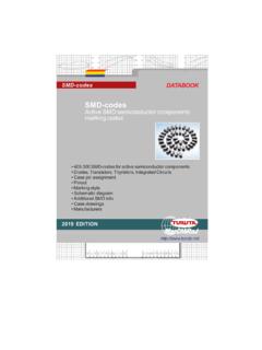
4 KW totem pole PFC solution with SiCMOSFETs, thyristor SCRs and digital controlInnovative topology for D-SMPS, EV charging and motor % peak efficiencyPeak inrush current tuningVery low THD and high power factorSTEVAL-DPSTPFC1 kW 1-ph Totem-pole PFC Input AC voltage: 85 VACup to 264 VAC Input AC frequency: 45 Hz up to 65 Hz DC output voltage: 400 VDC Maximum input current: 16 ARMS Ambient temperature: tested from 0 C up to 45 C Peak Efficiency: %with Compliant with: EN 55015 and IEC 61000-4-11 and IEC 61000-3-3 IEC 61000-4-5 surge: 4 kV IEC 61000-4-4 EFT burst: criteria A @ 4 kV min Cooling: forced air cooling with active fan Designed for operation with DC / DC converter Peak inrushcurrent tuningSTEVAL-DPSTPFC1 kW 1-ph Totem-pole PFCVoutSTGAP2SL400 VDCSTGAP2 SNSCTW35N65G2 VSilicon carbide MOSFET 650 V, 45 ATN3050H-12 WYSCR Thyristor30A % efficiency at full loadKey Products: SCTW35N65G2V (SiCMOSFET) TN3050H-12GY (SCR Thyristor) STGAP2AS (Galvanic insulated gate driver) STM32F334 (32-bit MCU) VIPer26LD (converter for aux.)
5 PS)Digital bridgeless PFC with inrush limiterSTEVAL-DPSTPFC1 operation during inrush limitationThe SCR gate signals limit the AC inrush current by sweeping triggering angle backward from 180 to 0 VACIACVDCSCR2 SCR1 VAC> 0 VAC< 0S2 VACIACVDCSCR1 SCR2S1 LAODS2 VACIACVDCSCR1 SCR2S1 LAODD igital bridgeless PFC with inrush limiterSTEVAL-DPSTPFC1 mosfets control IL S1S2 DTDT= 200nsSiCMOSFETs operate in safe synchronous conduction mode to optimize efficiencyLAODS2 VACILHVDCSCR1 SCR2S1IL (2A/div) S1 (2V/div)S2 (2V/div)HVDC (100V/div) Results: efficiency & THDVAC= 230 VRMS@ 50 Hz, Tamb= 25 C024681012141618909192939495969798995001 00015002000250030003500 THD (%)Effiieny (%)POUT (W)High Efficiency over complete load range Very low THD in medium / high loadResults: Load variation VAC= 230 VRMS@ 50 Hz, POUT= kW (100%)HVDCS1_CNTRLS2_CNTRLVACIACIHVDCLoa d variation from 0% to 100% Load variation from 100% to 0% Excellent Transient Load Variation thanks to feed forward digital implementation Results.
6 Power device temperaturesVAC= 230 VRMS@ 50hz, POUT= kW, tamb= 28 C, FAN ONLow side SiC MOSFETHigh side SiC MOSFETHigh side SCRThe board is equipped with Over Temperature Protection mounted on the heatsinkKey power product familiesA real boost for efficient high power designsHigh reliability and heatsink reductionVery high temperature handling capability(max. TJ = 200 C for SiCMOSFETs, max TJ = 150 C for SCRs)Higher system efficiencyThe most innovative SCR thyristor portfolioStrong & wide SCR rangeHigh TemperatureApplicationsHigh performance characteristicsSensitive Gate(X, P, TS)Standard Gate(TYN, TXN, TN & BTW)High Temperature(TNxxH-12) : 600 V to 1200 VIGT: 5 A to 50 mAITRMS: 12 A to 80 ATJ: 150 C 1200V thyristor SCRs rangeHVACR enewableCritical Power UPSC harging StationsIE3 Motor DrivesSmart EnergyReliable and compact designs in new AC / DC functionsTO-247D PAKTO-220 ABTOP3 InsulatedACEPACK SMITTO-247 LLCommercial PartCurrent(ARMS)Surge(A10ms)Trigger(mA) dV/dt(V/ s)PackageIndustrial Grade 1200 V , 125 CTYN1212RG1212015200TO-220TN2540-12G2530 0401500D2 PAKTYN1225RG25300401500TO-220TN4050-12PI 4040050500 TOP3-IBTW69-1200N50700501000 TOP3TN6050-12PI60700501000 TOP3-IAutomotive Grade 1200V , 150 CTN3050H-12GY30300501000D2 PAKTN3050H-12WY30300TO-247TN5050H-12WL50 400TO-247 LLTN6050HP-12WY80600TO-247TN8050H-12WL80 720TO-247 LLNEW = Light BlueGen2 650V SiCMOSFET product rangeAutomotiveGradeThe best RDS(on)
7 Vs Qgtrade-off Enalesnew technology platform with outstanding Figure Of Merit Excellent system efficiency and reduced cooling requirements Very low on-state resistance 200oC maximum junction temperature Very fast and robust intrinsic body diode Industrial and Automotive Grade qualified Charger Stations and On-Board Chargers PFC -SMPS for Industrial, Telecom & Class-D Audio Amplifiers Traction inverters in HEV and BEV Motor drives DC-DC convertersKey FeaturesTypical ApplicationsPart NumberVDS [V]RDS(on) Typ@25 C [ ]Id [A]PackageHiP247 HiP247-LLHiP247-4 LLH2 PAK-7 LTjmax= 200 CTjmax= 175 C650 Gen2 (Vgs=18V) kV Isolation 4 A sink and source current Single channel Active Miller Clamp or GON/GOFF pins kV Isolation 4 A sink and source current Dual channel Compact layout Industrial gradeSO16 NSO8 NIsolated Gate DriversSTGAP2S & STGAP2 DSTGAP2 SSTGAP2 DDifferent flavors for different needsRenewableSTGAP2S1700V, 4A isolated gate driver Active High & Active Low input pins, for HW interlocking STGAP2SM: Separated outputs option for easy gate driving adjustment STGAP2 SCM: Miller CLAMP pin option to avoid induced turn-on Negative gate drive ability SO8 Package 3V3 / 5 V logic inputs (logic thresholds 1/3, 2/3 of VDD ) Up to 26 V supply voltage 4 A Sink/Source current capability Short propagation delay.
8 80 ns UVLO Function Stand-by function 100 V/ns CMTI High voltage rail up to 1700 V Temperature shut-down protection STMicroelectronics -All rights logo is a trademark or a registered trademark of STMicroelectronics International NV or its affiliates in the EU and/or othercountries. For additional information about ST trademarks, please refer to All other product or service names are the property of their respective you