Transcription of TUNNEL-DIODE MICROWAVE AMPLIFIERS - jhuapl.edu
1 tunnel diodes provide a means of low-noise MICROWAVE amplification, with the AMPLIFIERS using the negative resistance of th e tunnel diode to amplification by reflection. The tunnel diode and its assumed equivalent circuit are discussed. The concept of negative-resistance reflection AMPLIFIERS is discussed from the standpoints of stability, gain, and noise performance. Two amplifi,er configurations are shown. of which the circulator-coupled type 1'S carried further into a design fo/' a C-band amplifier. The result 1'S an amph'fier at 6000 mc/s with a noise figure over 380 mc/s. An X-band amplifier is also reported. C. T. Munsterman TUNNEL-DIODE MICROWAVE Recent advances in TUNNEL-DIODE fabrication techniques have made the tunnel diode a practical, low-noise, MICROWAVE amplifier.
2 Small size, low power requirements, and reliability make these devices attractive for missile application, es-pecially since receiver sensitivity is significantly improved, with resulting increased homing time. Work undertaken at APL over the past year has resulted in the unique design techniques and hard-ware discussed in this Low-Noise MICROWAVE Amplification The need for low-noise MICROWAVE amplification can be seen when the system noise figure is con-sidered. The overall noise figure, F, of a system consisting of n stages is given by the following expression: F = FI + F2 -1 + F3 -1 + .. G] GIG'!, * The author wishes to acknowledge the assistance of E.
3 E. Skelton and S . W. May of APL in the fabrication and testing of the tunnel diode AMPLIFIERS . 2 where the gain of the ith stage is denoted by G i and its noise figure by F i. This equation shows that stages without gain ( G < 1 ) contribute greatly to the overall system noise figure, especially if they are not preceded by some source of gain. If a low-noise-amplification device can be located near the source of the signal, the contribution from the successive stages can be minimized by making G] sufficiently large, and the overall noise figure is then that of the amplifier Fl. If low-noise ampli-fication is not available until the second or third stages, then a high-noise figure results.
4 This latter case pertains to many MICROWAVE systems in which down conversion is necessary before amplification can take place. The inclusion of TUNNEL-DIODE AMPLIFIERS in systems formerly using down con-version and then amplification results in noise figure improvements generally greater than 6 db. When TUNNEL-DIODE AMPLIFIERS are used instead of traveling wave tubes, they simplify greatly the required power supplies, reduce power dissipation, and make warm-up time n egligible. It should be pointed out, however, that traveling wave tubes are superior in available gain and maximum out-put power. Thus, TUNNEL-DIODE AMPLIFIERS are usu-ally considered only for receiver applications where signal levels are well below TUNNEL-DIODE saturation.
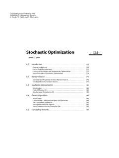
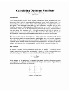
5 APL Technical Digest The tunnel diode The discovery of the tunnel diode was made in the 1950's during research on back diodes, that is, on diodes whose reverse conduction is greater than forward conduction. 1 High reverse conduction can best be pictured as the limiting case of the zener breakdown. As theory had predicted, this reverse breakdown voltage could be decreased by higher doping concentrations of the semiconductor mate-rial. The result of these high impurity levels was not only an immediate reverse conduction, but un-expected negative Figure 1 A shows a typical TUNNEL-DIODE voltage-current characteristic. The high reverse conduction and negative resist-ance region can be compared to the conventional diode curve shown by the broken line.
6 Design Considerations The concept of a negative resistance producing gain can best be shown by using simple transmis-sion line theory. A transmission line of character-istic impedance Zo is terminated in an impedance of value Z d. The loss of power because of reflec-tion is given by the square of the voltage reflection coefficient, f. This coefficient is defined in terms of the impedances by the relationship f = Zd -Z o . Z d + Zo For posItlve impedance this is less than unity, as expected. But if Z d is a negative impedance, as a tunnel diode could be, a voltage reflection coeffi-cient greater than unity can result. The power gain, or voltage reflection coefficient squared, is then greater than one (Z d is now assumed nega-tive).
7 I-Zd -Zol2 11 + Z O/ZdI2 Gam = 1[/2 = -Zd + Zo = 1 -Z O/Zd The ratio of ZO/Zd for high gam is close to one. For a perfect match (Zd = Z o), oscillation re-sults. The necessity of impedance control is then the main problem of designing TUNNEL-DIODE am-plifiers. For a certain desired gain a certain imped-ance ratio must exist. For a given bandwidth this 1 L. Esaki, "New Phenomenon in Narrow Germanium pen Junc-tions," Phys. Rev., 109, 1958, 603-604. 2 L Esaki "Fundamentals of Esaki tunnel diode in Circuit Appli-cati~ns," Monograph on Radio Waves and Circuits (ed. S. Silver) Elsevier Publishing Co. , Amsterdam, 1963, 359-373. May-June 1965 ratio must be constant over the band; for stability it cannot be unity since unity match represents an unstable condition.]
8 TUNNEL-DIODE AMPLIFIERS are usually designed for less than 20-db gain to assure stable operation with expected diode resistance variation. A low-impedance DC source is required for stable biasing; this is illustrated in Fig. 1A. The two load lines shown represent the circuit resistance shunt-ing the tunnel diode . The high-impedance load line intersects the voltage-versus-current curve of the tunnel diode in three places. The two positive I-Z W Vll-(5Vl Z6 u -- tunnel diode ---CONVENTIO NA L diode TYPICAL VALUES FOR A V GERMANIUM tunnel diode II' = I 7 ma Ron = -78 !l ~o:~~~8~ -DESIRED OPERA~~: I~~INT OL-_____ ~I _____ O~F_M_I_N_IM_U_M __ N_O_I_SE _____ C~ ~a= VOLTAGE Fig.)
9 I-- TUNNEL-DIODE bias voltage plotted against (A) current, (8) resistance, and (C) noise constant. resistance intercepts are stable and are utilized in computer applications of the tunnel diode . For amplification a stable negative resistance is desired. A load line that results in a single valued bias point within the negative resistance region is also shown in Fig. lA. The requirement for this load line is that the external circuit resistance (load line) be less than the magnitude of the minimum negative resistance, Rm, available from the tunnel diode . This minimum resistance is indicated in Fig. 1 B. 3 The low-resistance shunt on the tunnel diode re-quired for biasing introduces two problems.
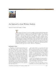
10 The first is that noise currents from this resistor must be isolated from the tunnel diode in order to pre-serve low-noise performance. Secondly, this resist-ance must be isolated from the tunnel diode at desired frequencies of amplification in such a way that a negative resistance is available for amplifi-cation. This second problem can be illustrated by con-sidering the equivalent resistance, Req, of two parallel resistors, Rl and R'.!.. R,R .. Reo = R, + -Re If R 2 is a negative resistance, Req will be negative provided R] is greater than I R 21: If these resistors are isolated by an inductance, AC stability becomes a problem. TUNNEL-DIODE Equivalent Circuit The accepted equivalent circuit of a tunnel diode is shown below : R,q is the resistance of the bulk material and contacting plates.