Transcription of AN12.14 Remote Thermal Sensing Diode Selection Guide
1 2014 Microchip Technology application note is aimed at designers who buildsystems that use Thermal sensors with Remote diodes;specifically, Remote diodes that are discrete bipolarjunction transistors (BJTs). Information presented here organizes important criteriafor selecting the Remote Sensing Diode to use withMicrochip's high accuracy, low cost Remote diodethermal sensors. Microchip does produce temperature sensors that aredesigned to work specifically with CPU Thermal , these discussions are about selecting an appropri-ate BJT, as well as providing a list of acceptable BJTs,several are this application note, the phrase remotediode-connected transistor refers to a discrete, Diode -connected (Base-Collector junction shorted)
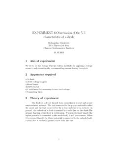
2 Application note assumes that the reader hasworking knowledge of temperature Sensing that usesdiode-connected is a practical approach for selecting a remotediode-connected transistor to use with a thermalsensor, as illustrated in Figure 1. Discussions of the semiconductor parameters of thetransistor that affect the accuracy of temperature mea-surement are included here as the requisite feature ofa Remote Thermal Sensing Diode . A short table of qualified discrete 2N3904 NPN transis-tors is provided here. It lists devices from other manu-facturers that have been tested and met establishedstandards of 1:Block Diagram of a Typical Temperature Sensing :Wayne LittleMicrochip Technology SensorDPDNR emoteDiode-ConnectedTransistorSMBusSyste mControllerwithSMBusInterfaceSMBusInterf aceRemote Thermal Sensing Diode Selection 2 2014 Microchip Technology PARAMETERST hese three semiconductor parameters are the primaryfactors when considering Diode -connected transistorsin temperature Sensing applications.
3 Ideality Factor ( ) Forward Current Gain (beta or hFE) Series Resistance (RS)Ideality Factor ( )The ideality factor is a parameter in the Diode current-voltage relationship. It approaches a value of whenthe carrier diffusion dominates the current flow, andapproaches when the recombination current domi-nates the current flow. This term is a constant on anyparticular device, though it can vary among individualdevices. Temperature sensors are calibrated during the final testto provide accurate readings with a Diode that has atypical ideality factor. For the purposes of this docu-ment, the typical ideality factor value is expressed as ASSUMED and the ideality factor value of the user sdiode-connected transistor is expressed as temperature indicated by a temperature sensor willinclude an error from the real temperature, as definedby the equation in Equation 1.
4 To use this equation, thetemperature values must be converted to the Kelvinscale. The result will be incorrect if the values usedreflect the Celsius or Fahrenheit 1:TEMPERATURE ERROR DUE TO IDEALITY FACTOR MISMATCHG enerally, a 2N3904 transistor is the preferred remotediode. Several samples of each of the transistors listedin Ta b l e 1 were evaluated and their ideality factor wasdetermined to be ~ (Typically, the ideality factoris not be stated in the data sheet for a transistor.) Whiletransistor devices other than the ones cited here couldbe used; to be confident of accurate operation, theyshould be qualified before Equation 1, the ideality factor value that the tempera-ture sensor is calibrated for is ASSUMED and the actualideality factor value of the Diode -connected transistor is REAL.
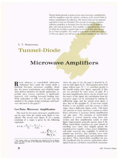
5 In this equation, the temperature measurementerror is not a constant offset, but increases as TREAL,the temperature of the Remote Diode -connectedtransistor, 2 shows the temperature-measurement errorthat is induced solely from the differences between ASSUMED and REAL. In this figure, ASSUMED is ,a typical ideality factor value for a 2N3904 NPN Diode -connected transistor. Temperature sensors are typi-cally calibrated in the range of the 2N3904 ( )because this is also very similar to the ideality factor ofthe majority of substrate Diode -connected transistorsthat are found on CPUs and 2:Temperature Error vs.
6 Ideality Factor of Diode (with IC trimmed to ).Figure 2 also shows why true 2-terminal discretediodes are not used in temperature Sensing applica-tions instead of 3-terminal devices such as the discrete 2-terminal Diode , ideally, would perform intemperature Sensing applications as well as a thermaldiode would. However, characterization in the labsdetermined that discrete 2-terminal diodes typicallyhave an ideality factor much higher ( ) than ASSUMED of This discrepancy (between ASSUMED and REAL) would cause unacceptabletemperature measurement errors at all :Qualification of these devices is ideallyperformed by obtaining data, on theparameters described in this applicationnote, from the device manufacturer.
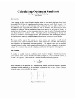
7 Pre-cision Thermal equipment is required tomeasure the parameters. Contact yourMicrochip Field Applications Engineer foradditional REAL ASSUMED-------------------------------- TREAL =TABLE 1:TYPICAL IDEALITY FACTOR VALUES FOR 2N3904 Diode -CONNECTED TRANSISTORSM anufacturerTypical Ideality FactorROHM Semiconductor CO., Technologies Semiconductor 20406080100 Measured Temperature Error ( C) Real Temperature ( C) 2014 Microchip Technology Current Gain (beta or hFE)A typical temperature sensor forces two fixed currents(IF1 and IF2) into the Thermal Diode to measuretemperature, as shown in Figure 3:Two Current temperature sensor measures the voltage, VBE,which is developed based on the collector current; notthe emitter 2:IDEAL DIODEThe forward current gain (beta) of a transistor is not aconstant over all operating conditions, but varies overtemperature and as a function of IC.
8 The variation inbeta over temperature does not induce temperaturemeasurement error. However, if the transistor has alarge variation in beta as a function of IC, thetemperature reading can be inaccurate, due to beta-induced the value of beta is relatively constant over the rangeof forced emitter currents, then the ratio of IC2:IC1remains equal to the ratio of the two forced emittercurrents and induces no error. It only becomes aproblem when the beta variation causes a mismatchbetween the IC2:IC1 ratio and the IE2:IE1 3 shows the error induced from thenon-constant value of beta at the two currents.
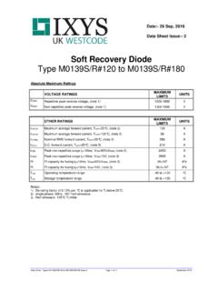
9 F1 rep-resents the beta of the transistor at the current value IF1while F2 represents the beta at the current value IF2. N represents the fixed ratio of the two forced (IE1 andIE2) currents. If beta is constant over the range of thetwo currents ( F1 = F2), then there is no temperaturemeasurement error induced because of beta 3:TEMPERATURE ERROR DUE TO BETA VARIATIONTemp Sensor ICRemote Diode (2N3904)Voltage toTemperatureConversionVDDVBEIF1IF2 IBICIETVBE2 VBE1 q k1nIC2IC1--------- ---------------------------------------- ----------= TERRORTREAL1n F21 F1+ F11 F2+ ---------------------------------------- -- 1n N ---------------------------------------- -------------- = 4 2014 Microchip Technology 4 presents a plot of allowable beta variation overthe sensor s sourced current range (10 400 A)
10 To beable to still maintain at least 1 degree accuracy at 70 beta of the transistor must reside between the twolines in the plot, over the extremes of the current rangeof the temperature sensor, in order to maintain 1 Caccuracy with the selected Diode -connected x-axis represents the beta of the Diode -connectedtransistor at IF1, while the y-axis is for the beta at over the sensor s sourced current 4:Allowed Beta Variations for 1 Degree Accuracy at 70 5 shows typical values of transistor beta for alimited sample of these devices. These devices werecharacterized in Microchip characterization labs. Thisdata should not to be used as a guaranteed value forthe specific transistor, only a typical representation forthe limited quantity tested by 5:Typical Beta Values for 2N3904 Transistors at 23 2 Beta 1 (Ic/Ib)Collector CurrentTypical Beta Values for 2N3904 Transistors at 2014 Microchip Technology conclusion to draw from Figure 4, Figure 5 andTable 2 is that for the set of 2N3904 transistors testedby Microchip, the beta was consistently high and measured value of beta easily resides inside the 2lines of Figure 4, over the entire temperature sensor ssourced current range.