Transcription of Ian Williams TI Precision Designs: Verified Design Active ...
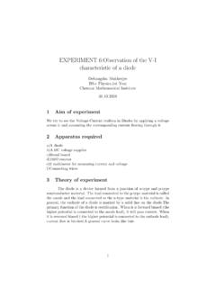
1 An IMPORTANT NOTICE at the end of this TI reference Design addresses authorized use, intellectual property matters and other important disclaimers and information. TINA-TI is a trademark of Texas Instruments WEBENCH is a registered trademark of Texas Instruments TIDU034-December 2013-Revised December 2013 Active Volume Control for Professional Audio 1 Copyright 2013, Texas Instruments Incorporated Ian Williams TI Precision Designs: Verified Design Active Volume Control for Professional Audio TI Precision Designs Circuit DescriptionTI Precision Designs are analog solutions created by TI s analog experts. Verified Designs offer the theory, component selection, simulation, complete PCB schematic & layout, bill of materials, and measured performance of useful circuits.
2 Circuit modifications that help to meet alternate Design goals are also discussed. This split-supply, high-performance volume control circuit attenuates a professional line-level audio signal with minimal distortion and noise. An input buffer preserves the behavior of the system independent of the audio input source impedance. A radio frequency (RF) filter on the circuit front end removes noise from outside the audio band, while a bidirectional transient voltage suppressor (TVS) diode protects against overvoltage spikes. Design Resources Design Archive All Design files TINA-TI SPICE Simulator OPA1604 Product Folder Ask The Analog Experts WEBENCH Design Center TI Precision Designs Library -15V+15V+R4+R3P1+R8R9+R10U1AU1BU1CU1DC1C 7C6 Audio InputAudio Output 2 Active Volume Control for Professional Audio TIDU034-December 2013-Revised December 2013 Copyright 2013, Texas Instruments Incorporated 1 Design Summary The Design requirements are as follows: Supply Voltage: 15 V Input: Professional line-level audio signal (+4 dBu / VRMS) Input impedance: 20 Output: Professional line-level audio signal (+4 dBu / VRMS) Total harmonic distortion + noise (THD+N) ratio at 1 kHz.
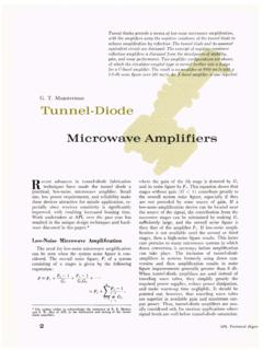
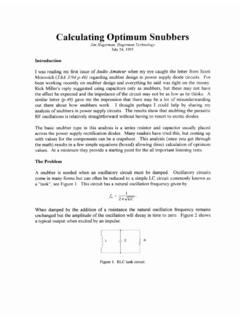
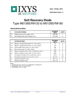
3 Ideal gain characteristic: -20dB over full potentiometer rotation Gain deviation (30% to 100% potentiometer rotation): dB Off gain: -100 dB The Design goals and performance are summarized in Table 1. Figure 1 depicts the measured transfer function of the Design . Table 1. Comparison of Design Goals, Simulation, and Measured Performance Goal Simulated Measured THD+N ratio at 1kHz Gain deviation (regulated region) dB dB dB Off gain -100 dB dB -103 dB (dB)Potentiometer Rotation (%)MeasuredIdeal (-20 dB) Figure 1: Measured Gain Characteristic TIDU034-December 2013-Revised December 2013 Active Volume Control for Professional Audio 3 Copyright 2013, Texas Instruments Incorporated 2 Theory of Operation A more complete schematic for this Design is shown in Figure 2.
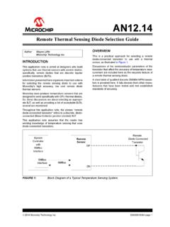
4 The transfer function of the circuit is based on the first stage gain (set by the ratio of R3 and R4), the rotation of potentiometer P1 (expressed as a decimal), and the second stage gain (set by the ratio of R8 and R9). TVS diode D1 protects the circuit from harmful transient energy. A second order low pass filter which attenuates energy in the RF frequencies is created by the audio signal source impedance, D1 s junction capacitance, R5, and C5. The remaining components are used for ac coupling, amplifier input biasing, stability compensation, and power supply decoupling. R7-15V+15V+R4R6D1+R3P1+R8R9+ R10U1AU1BU1CU1DR5C5C4C9C8C2C1C7C6C3 Audio InputAudio OutputRF Filter and Input AmplifierBaxandall Volume Control Figure 2: Complete Circuit Schematic The transfer function for this Design is defined by the following equation: (1) 4 Active Volume Control for Professional Audio TIDU034-December 2013-Revised December 2013 Copyright 2013, Texas Instruments Incorporated Volume Controls The volume control is a critical component of any audio system.
5 Because of the dynamic nature of audio, and the amount of variance in the output amplitudes of different signal sources, it is necessary for a user to have control over the amount of gain provided by an audio circuit. The volume control should contribute no significant distortion or noise in order to preserve the integrity of the source audio signal. Human hearing spans a large dynamic range, so units of decibels (dB) are typically used to describe the power of audio signals. It is desirable for a volume control to have a gain characteristic which is linear in dB since the result is a very natural change in perceived volume as the user rotates the volume knob [1]. Potentiometer Characteristics Potentiometers, often called pots, are by the far the most common component used to control volume, and several different types of pots exist for this purpose.
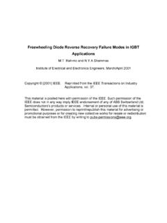
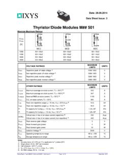
6 The three most common types, also called tapers, are the linear taper, logarithmic (or audio) taper, and reverse logarithmic (or reverse audio) taper. Figure 3 shows an approximate resistance characteristic of these tapers. 0102030405060708090100010203040506070809 0100 Resistance (%)Potentiometer Rotation (%)LinearLogarithmicRev. Logarithmic Figure 3: Common Potentiometer Characteristics Linear pots, usually given the code letter B, are simple devices where the amount of resistance is proportional to the amount of rotation. Logarithmic pots, usually given the code letter A, roughly approximate a logarithmic response by combining two linear slopes. Reverse logarithmic pots, usually given the code letter C, follow the same behavior as logarithmic pots but are constructed in reverse.
7 As you can see, any of these potentiometers on their own do not create a very accurate approximation of a true logarithmic response, at least for professional audio applications [1]. TIDU034-December 2013-Revised December 2013 Active Volume Control for Professional Audio 5 Copyright 2013, Texas Instruments Incorporated Baxandall Active Volume Control Several methods have been used in the attempt to better approximate a linear-in-dB response using pots. However, no solution provides the performance, flexibility, and simplicity of the circuit initially presented by Peter Baxandall in 1980 as part of an article in Wireless World magazine [1]. For this reason, a modified version of his circuit was chosen as the primary component of this reference Design .
8 Figure 4 shows the basic schematic of this circuit. P1+R8R9+U1CU1 DVOUTVIN Figure 4: Baxandall Active Volume Control [1] The Baxandall Active volume control circuit is a type of shunt-feedback control with two main advantages over other solutions. First, it achieves excellent logarithmic behavior with a linear pot, and second, its transfer function is not a function of the pot track resistance or any other discrete resistances. Rather, the gain characteristic is only a function of the percentage of pot rotation and the maximum gain set by the ratio of two resistors. This allows a standard-tolerance pot to be used with excellent results, and a dual linear pot can give good matching between channels of a stereo system [1].
9 This Design describes a single channel solution and therefore a single pot is used, but the same circuit can simply be copied for a stereo system. Active volume controls in general have several other advantages over their passive counterparts. The use of amplifiers allows for gain early in the signal chain, improving noise performance. The current drive capabilities of the amplifiers allow low resistance values to be used, which minimizes Johnson noise and capacitive crosstalk. Finally, the high input impedance and low output impedance of the amplifiers ensures a robust Design which, with some minor exceptions, maintains its performance independent of the source and load impedance [1]. 6 Active Volume Control for Professional Audio TIDU034-December 2013-Revised December 2013 Copyright 2013, Texas Instruments Incorporated Baxandall Active Volume Control Transfer Function The simplicity of Baxandall s circuit allows for a straightforward transfer function analysis.
10 For this analysis, potentiometer P1 is replaced with two discrete resistors: RX, which represents the percentage of pot resistance after the wiper, and R1-X, which represents the percentage of pot resistance before the wiper. Together these two resistors represent the total possible span of pot rotation. Figure 5 shows the modified circuit schematic. R1-x+R8R9+U1CU1 DVOUTRxVINVXi3i1i2 VXGain = G Figure 5: Modified Baxandall Volume Circuit for Transfer Function Analysis To analyze the transfer function, first define the voltage at the wiper as VX. Since amplifier U1C is configured as a non-inverting buffer, the voltage at the output of U1C is also equal to VX. VX is applied as the input to amplifier U1D, which is configured as an inverting amplifier with gain G.