Transcription of Ultralow Offset Voltage Operational Amplifier …
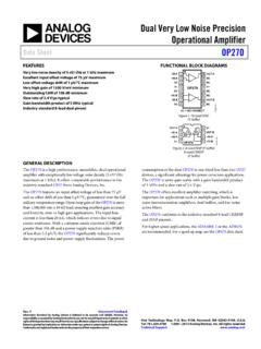
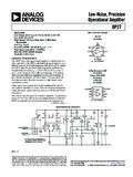
1 Ultralow Offset Voltage Operational Amplifier data Sheet OP07. FEATURES PIN CONFIGURATION. Low VOS: 75 V maximum VOS TRIM 1 8 VOS TRIM. Low VOS drift: V/ C maximum OP07. Ultrastable vs. time: V per month maximum IN 2 7 V+. Low noise: V p-p maximum +IN 3 6 OUT. Wide input Voltage range: 14 V typical V 4 5 NC. 00316-001. Wide supply Voltage range: 3 V to 18 V. NC = NO CONNECT. 125 C temperature-tested dice Figure 1. APPLICATIONS. Wireless base station control circuits Optical network control circuits The wide input Voltage range of 13 V minimum combined Instrumentation with a high CMRR of 106 dB (OP07E) and high input Sensors and controls impedance provide high accuracy in the noninverting circuit Thermocouples configuration. Excellent linearity and gain accuracy can be Resistor thermal detectors (RTDs) maintained even at high closed-loop gains.
2 Stability of offsets Strain bridges and gain with time or variations in temperature is excellent. The Shunt current measurements accuracy and stability of the OP07, even at high gain, combined Precision filters with the freedom from external nulling have made the OP07 an industry standard for instrumentation applications. GENERAL DESCRIPTION. The OP07 is available in two standard performance grades. The The OP07 has very low input Offset Voltage (75 V maximum for OP07E is specified for operation over the 0 C to 70 C range, OP07E) that is obtained by trimming at the wafer stage. These and the OP07C is specified over the 40 C to +85 C. low Offset voltages generally eliminate any need for external temperature range. nulling. The OP07 also features low input bias current ( 4 nA for the OP07E) and high open-loop gain (200 V/mV for the OP07E).
3 The OP07 is available in epoxy 8-lead PDIP and 8-lead narrow The low Offset and high open-loop gain make the OP07 SOIC packages. For CERDIP and TO-99 packages and standard particularly useful for high gain instrumentation applications. microcircuit drawing (SMD) versions, see the OP77. V+. 7 R2A1 R2B1. (OPTIONAL C1 R7. NULL). 1 8. R1A R1B. Q19. Q9 Q10. R9. Q7 Q8 Q11 Q12 OUT. 6. Q5 Q3 Q6 Q4. R3 Q27 C3 C2 Q17 R10. NONINVERTING Q16. INPUT 3 Q1 R5. Q21 Q23 Q26 Q20. R4 Q22 Q24 Q15. INVERTING Q25. INPUT Q2. 2 Q14 Q18. Q13 R6 R8. 4. V . 00316-002. 1 R2A AND R2B ARE ELECTRONICALLY ADJUSTED ON CHIP AT FACTORY FOR MINIMUM INPUT Offset Voltage . Figure 2. Simplified Schematic Rev. G. Information furnished by analog devices is believed to be accurate and reliable. However, no responsibility is assumed by analog devices for its use, nor for any infringements of patents or other rights of third parties that may result from its use.
4 Specifications subject to change without notice. No One Technology Way, Box 9106, Norwood, MA 02062-9106, license is granted by implication or otherwise under any patent or patent rights of analog devices . Tel: Trademarks and registered trademarks are the property of their respective owners. Fax: 2002-2011 analog devices , Inc. All rights reserved. OP07* PRODUCT PAGE QUICK LINKS. Last Content Update: 02/23/2017. COMPARABLE PARTS TOOLS AND SIMULATIONS. View a parametric search of comparable parts. analog Filter Wizard analog Photodiode Wizard EVALUATION KITS. EVAL-OPAMP-1 Evaluation Board DESIGN RESOURCES. OP07 Material Declaration DOCUMENTATION PCN-PDN Information Application Notes Quality And Reliability AN-573: OP07 Is Still Evolving Symbols and Footprints AN-649: Using the analog devices Active Filter Design Tool DISCUSSIONS.
5 data Sheet View all OP07 EngineerZone Discussions. OP07: Ultralow Offset Voltage Operational Amplifier data Sheet SAMPLE AND BUY. Product Highlight Visit the product page to see pricing options. Amplifier pricing where you want it, TECHNICAL SUPPORT. SOFTWARE AND SYSTEMS REQUIREMENTS. Submit a technical question or find your regional support JAN to Generic Cross Reference number. DOCUMENT FEEDBACK. Submit feedback for this data sheet. This page is dynamically generated by analog devices , Inc., and inserted into this data sheet. A dynamic change to the content on this page will not trigger a change to either the revision number or the content of the product data sheet. This dynamic page may be frequently modified. OP07 data Sheet TABLE OF CONTENTS. Features .. 1 Absolute Maximum Ratings.
6 6. Applications .. 1 Thermal Resistance ..6. General Description .. 1 ESD Pin Configuration .. 1 Typical Performance Characteristics ..7. Revision History .. 2 Typical Applications .. 11. 3 Applications Information .. 12. OP07E Electrical Characteristics .. 3 Outline Dimensions .. 13. OP07C Electrical Characteristics .. 4 Ordering Guide .. 14. REVISION HISTORY. 10/11 Rev. F. to Rev G 8/03 Rev. B to Rev. C. Changes to Features 1 Changes to OP07E Electrical Specifications ..2. Changes to OP07C Electrical Specifications ..3. 8/10 Rev. E. to Rev F Edits to Ordering Guide ..5. Changes to Ordering Guide .. 14 Edits to Figure 6 ..9. 7/09 Rev. D. to Rev E Updated Outline Dimensions .. 11. Changes to Figure 29 11 3/03 Rev. A to Rev. B. Changes to Ordering Guide .. 14 Updated Package Titles.
7 Universal 7/06 Rev. C. to Rev D Updated Outline Dimensions .. 11. Changes to 1 2/02 Rev. 0 to Rev. A. Changes to General Description .. 1 Edits to Changes to Specifications Section .. 3 Edits to Ordering Guide ..1. Changes to Table 4 .. 6 Edits to Pin Connection Drawings ..1. Changes to Figure 6 and Figure 8 .. 7 Edits to Absolute Maximum Ratings ..2. Changes to Figure 13 and Figure 14 .. 8 Deleted Electrical Characteristics .. 2 3. Changes to Figure 20 .. 9 Deleted OP07D Column from Electrical Characteristics .. 4 5. Changes to Figure 21 to Figure 25 .. 10 Edits to TPCs .. 7 9. Changes to Figure 26 and Figure 30 .. 11 Edits to High-Speed, Low VOS Composite Amplifier ..9. Replaced Figure 28 .. 11. Changes to Applications Information 12. Updated Outline Dimensions .. 13.
8 Changes to Ordering Guide .. 14. Rev. G | Page 2 of 16. data Sheet OP07. SPECIFICATIONS. OP07E ELECTRICAL CHARACTERISTICS. VS = 15 V, unless otherwise noted. Table 1. Parameter Symbol Conditions Min Typ Max Unit INPUT CHARACTERISTICS. TA = 25 C. Input Offset Voltage 1 VOS 30 75 V. Long-Term VOS Stability 2 VOS/Time V/Month Input Offset Current IOS nA. Input Bias Current IB nA. Input Noise Voltage en p-p Hz to 10 Hz 3 V p-p Input Noise Voltage Density en fO = 10 Hz nV/ Hz fO = 100 Hz3 nV/ Hz fO = 1 kHz nV/ Hz Input Noise Current In p-p 14 30 pA p-p Input Noise Current Density In fO = 10 Hz pA/ Hz fO = 100 Hz3 pA/ Hz fO = 1 kHz pA/ Hz Input Resistance, Differential Mode 4 RIN 15 50 M . Input Resistance, Common Mode RINCM 160 G . Input Voltage Range IVR 13 14 V. Common-Mode Rejection Ratio CMRR VCM = 13 V 106 123 dB.
9 Power Supply Rejection Ratio PSRR VS = 3 V to 18 V 5 20 V/V. Large Signal Voltage Gain AVO RL 2 k , VO = 10 V 200 500 V/mV. RL 500 , VO = V, VS = 3 V4 150 400 V/mV. 0 C TA 70 C. Input Offset Voltage1 VOS 45 130 V. Voltage Drift Without External Trim4 TCVOS V/ C. Voltage Drift with External Trim3 TCVOSN RP = 20 k V/ C. Input Offset Current IOS nA. Input Offset Current Drift TCIOS 8 35 pA/ C. Input Bias Current IB nA. Input Bias Current Drift TCIB 13 35 pA/ C. Input Voltage Range IVR 13 V. Common-Mode Rejection Ratio CMRR VCM = 13 V 103 123 dB. Power Supply Rejection Ratio PSRR VS = 3 V to 18 V 7 32 V/V. Large Signal Voltage Gain AVO RL 2 k , VO = 10 V 180 450 V/mV. OUTPUT CHARACTERISTICS. TA = 25 C. Output Voltage Swing VO RL 10 k V. RL 2 k V. RL 1 k V. 0 C TA 70 C. Output Voltage Swing VO RL 2 k 12 V.
10 Rev. G | Page 3 of 16. OP07 data Sheet Parameter Symbol Conditions Min Typ Max Unit DYNAMIC PERFORMANCE. TA = 25 C. Slew Rate SR RL 2 k 3 V/ s Closed-Loop Bandwidth BW AVOL = 1 5 MHz Open-Loop Output Resistance RO VO = 0, IO = 0 60 . Power Consumption Pd VS = 15 V, No load 75 120 mW. VS = 3 V, No load 4 6 mW. Offset Adjustment Range RP = 20 k 4 mV. 1. Input Offset Voltage measurements are performed by automated test equipment approximately seconds after application of power. 2. Long-term input Offset Voltage stability refers to the averaged trend time of VOS vs. the time over extended periods after the first 30 days of operation. Excluding the initial hour of operation, changes in VOS during the first 30 operating days are typically V. Refer to the Typical Performance Characteristics section.