Transcription of Write your own generic SPICE Power Supplies …
1 1 Write your own generic SPICE Power Supplies controller modelsChristophe BASSON ovember 1996 Manuscript for PCIM USSimulating the switching behavior of a Switch Mode Power Supply (SMPS) is not always an easy is especially true if the designer wants to use an exact SPICE model for the Pulse Width Modulator(PWM) controller which will be used in the design. The PWM model may exist, but its syntax may beincompatible with your simulator. If the model has not been created, the debate over whether or not to do thesimulation is closed! The solution that is proposed in this article consists of writing your own generic model ofthe PWM controller and then adapting its intrinsic parameters to comply with the real one you are using.
2 Fixedfrequency Current Control Mode (CCM) and Voltage Control Mode (VCM) models will be thoroughly coveredin this article, as well as the model translation between different Berkeley B element, the standard behavior elementAn efficient PWM model that is easy to model must include functions that are generic . For instance, itwould not be clever to model an internal current comparator with the complete transistor architecture of aLM311 or a LM193. Fortunately, there is a simple in-line equation that can describe the perfect comparisonfunction. By adding some passive elements to incorporate various effects (propagation delay, input offsetvoltage, etc.) we can achieve the functionality we need without sacrificing the simulation non-linear controlled source, or B element, is part of Berkeley SPICE3, which was released to thepublic domain in 1986.
3 Depending on the compatibility of your SPICE 3 simulator, the corresponding syntaxmay vary significantly. B elements can be linear or non-linear current or voltage sources. Some vendors haveexpanded the B element syntax to include BOOLEAN and IF-THEN-ELSE functions. For INTUSOFT sIsSpice4 (San Pedro, CA) and CADENCE s Analog WorkBench SPICE Plus (San-Jose, CA), the writing of I orV math equations using B elements is the same because both are SPICE 3 compatible. For example,current/voltage generators whose current depends on various nodes can be expressed as:B1 1 0 I = V(5,8)*100*V(10)/(V(8)+V(12)); IsSpice or AWB current sourceB2 2 0 V= V(9,8)*500*V(12); IsSpice or AWB voltage sourceMICROSIM s PSpice (Irvine, CA) has departed from the Berkeley standard and uses a differentsyntax.
4 PSpice modifies the standard calls for dependent voltage controlled sources (E and G elements). Theequivalent PSpice examples are as follows:G1 1 0 VALUE = { V(5,8)*100*V(10)/(V(8)+V(12)) }; PSpice current sourceE2 2 0 VALUE = { V(9,8)*500*V(12) }; PSpice voltage sourceImplement your logical operationsAs stated in the above paragraph, BOOLEAN and IF-THEN-ELSE expressions have become a part ofmost vendors B elements. Their implementation also depends on the SPICE simulator. INTUSOFT exploitsthe concept of binary voltage, that is to say, a node value which is lower or higher than a user-definedthreshold can be associated with 1 or 0. This threshold is driven by the keyword LTHRESH, whose value is setvia a.
5 OPTIONS line. Two other options, LONE and LZERO, will define the HI and LO electrical values whichare delivered by a B element source when it is performing such BOOLEAN operations. A simple NAND equation between two nodes is simply expressed as:BNAND 3 0 V= ~ ( V(1) IsSpice complemented (~) AND operation between V(1) and V(2)Because the other SPICE simulators do not directly support this syntax, it would be much easier toadopt a simpler expression in order to simplify any further translations. If we pass the logical thresholdsdirectly into the equation, we obtain the following IsSpice IF-THEN-ELSE statement:BNAND 3 0 V= (V(1)>800M) & (V(2)>800M)?)
6 0V: 5V2In other words,IF V(1) is greater than 800mV AND V(2) is greater than 800mV, THEN V(3,0)=0V; ELSE V(3,0)=5 VNow the translation to AWB and PSpice syntax is more straightforward:E_BNAND 3 0 VALUE = { IF ( (V(1)>800M) & (V(2)>800M), 0V, 5V ) }; PSpice NAND gateBNAND 3 0 V = IF ( (V(1)>800M) && (V(2)>800M), 0, 5 ); AWB NAND gateNote that the AWB parser does NOT accept suffixes for the passed numerical values and the &&symbol is doubled as in the C language to distinguish a logical AND from a binary AND. The diversity inimplementing the B elements is only bound by the user s imagination. What we have shown above is only asmall part of the possibilities offered by Behavioral Modeling via the B your simulator does not support B element modeling, the situation becomes complex.
7 Some examples on howto model the logical functions with SPICE2 syntax are given at the end of this s an application example, a simple voltage limiter which limits the differential voltage of nodes 1and 2 between 100mV and 1V:E1 3 0 TABLE {V(1)-V(2)} 100M,100M 1,1; PSpiceB1 3 0 V = IF ( V(1,2) < 1, IF (V(1,2) < 100M, 100M, V(1,2)),1); AWB (No suffixes!)B1 3 0 V = V(1,2) < 100MV ? 100M : V(1,2) > 1 ? 1 : V(1,2); IsSpiceIn other words,IF V(1,2) is less than 100mV, THEN V(3,0)=100mV; ELSE IF V(1,2) is greater than 1V, THEN V(3,0)=1V,ELSE V(3,0)=V(1,2)B elements switch in essentially a zero time span. This characteristic may create convergence problemson transitions associated with these perfect sources.
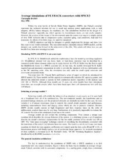
8 We recommend that you tailor the output switching timesin a more realistic manner. A simple RC network is suitable for this purpose. A perfect comparator whichaccounts for these conditions is given below. We have included it in a SUBCIRCUIT in order to highlight thephilosophy of constructing your own models:.SUBCKT COMP 1 2 3*(+)(-)OUTE1 4 0 VALUE = { IF ( V(1) > V(2), 5V, 0 ) }; PSpice syntax; IsSpice Syntax: B1 4 0 V=V(1) > V(2) ? 5 : 0RD 4 3 100; RC networkCD 3 0 100P; to slow down COMPNow that we have reviewed the basics of generating in-line equations, let s dip into the nitty-gritty of aconstant frequency CCM PWM mode controllers, a well known architectureFigure 1, the internal circuitry of a generic single output CCM PWM + - + - ClockError LatchOUTFBISENSEVREFO utput DriverMax.
9 1 The modelling of such a block consists of: a) defining and testing each subcircuit individually, andb) assembling all of these domino-like circuits to form the complete generic model . All individual blocksshould be tested before they are used within larger models. Below are some recommendations that will easeyour task: Draw the symbol of your generic model with your favorite schematic capture tool. Once this is done, youwon t have to worry about incorrect pin connections (as you would if you were creating a SPICE netlist witha text editor). Internal subcircuit testing is simplified since you may then access the connection pins directlyin the schematic model , and the pin passing process (from schematic to netlist) is performed automatically.
10 Place comments on every pertinent line, either with a * in column one (for a complete line), or a ; immediately preceding a comment within a line. Also, use different commented header names for eachsection of code within the listing. Use descriptive names for the components you assemble in the subcircuit netlist, VCLOCK for a clocksource, RDUM for a dummy load, etc. Use subcircuits whenever a function is called more than once. Even if the function is only called once, youcan create a subcircuit and therefore simplify the netlist. This will also facilitate the writing of new modelsbecause the .SUBCKT functions are easily pasted into the netlist.