AN2867 Application note - STMicroelectronics
is the anti-resonant frequency when impedance Z tends to infinity. Using equation (1), it is expressed as follows: Fa Fs 1 Cm C0 = + -----The region delimited by F. s. and F. a. is usually called the area of parallel resonance (shaded area in . Figure 2). In this region, the crystal operates in parallel resonance and behaves as
Download AN2867 Application note - STMicroelectronics

Information
Domain:
Source:
Link to this page:
Documents from same domain

Low-power dual operational amplifier - st.com
www.st.comFebruary 2016 DocID2471 Rev 17 1/24 This is information on a product in full production. www.st.com LM2904, LM2904A Low-power dual operational amplifier

AN3128 Application note - st.com
www.st.comJune 2011 Doc ID 16918 Rev 5 1/105 AN3128 Application note STM32 embedded graphic objects/touchscreen library Introduction This library is a firmware package which contains a collection of routines, data structures,

AN4767 Application note - st.com
www.st.comDocID028380 Rev 2 7/16 AN4767 Dual bank use cases 15 With dual bank, all the manipulation with the other bank is just another task of the main program.

AN3155 Application note - st.com
www.st.comOctober 2016 DocID17066 Rev 7 1/37 1 AN3155 Application note USART protocol used in the STM32 bootloader Introduction This application note describes the USART protocol used in the STM32 microcontroller

USB Power Delivery and Type-C - st.com
www.st.comUSB Type -C Overview USB Power Delivery specification introduces USB Type-C receptacle, plug and cable; they provide a smaller, thinner and more robust alternative to existing USB interconnect.

Datasheet - L78 - Positive voltage regulator ICs - …
www.st.comTO- 2 2 0 TO-2 2 0 F P DPAK D² PAK Features • Output current up to 1.5 A • Output voltages of 5; 6; 8; 8.5; 9; 12; 15; 18; 24 V • Thermal overload protection

AN2867 Application note - st.com
www.st.comMay 2017 DocID15287 Rev 11 1/43 1 AN2867 Application note Oscillator design guide for STM8AF/AL/S and STM32 microcontrollers Introduction Many designers know oscillators based on Pierce-Gate topology (hereinafter referred to as

AN4776 Application note - st.com
www.st.comMay 2017 DocID028459 Rev 2 1/73 1 AN4776 Application note General-purpose timer cookbook Introduction The timer peripheral is part of …

120-volt, 100-watt, DMOS audio amplifier with mute …
www.st.comSeptember 2010 Doc ID 6744 Rev 8 1/21 21 TDA7293 120-volt, 100-watt, DMOS audio amplifier with mute and standby Features Multipower BCD technology Very high operating voltage range (±50 V)

Electronic transformer for a 12V halogen lamp - …
www.st.comAPPLICATION NOTE AN528/0999 1/4 ELECTRONIC TRANSFORMER FOR A 12V HALOGEN LAMP by P. Fichera, R. Scollo 1. INTRODUCTION Lighting that uses halogen lamps is commonly found
Related documents

Agilent Basics of Measuring the Dielectric Properties of ...
academy.cba.mit.eduResonant cavity .....25 Parallel plate .....27 Comparison of methods ... across a parallel plate capacitor, more charge is stored when a dielectric material is between the plates than if no material (a vacuum) is between the plates. The dielectric material increases the storage capacity of the capacitor

RLC Resonant Circuits - University of Cambridge
mlg.eng.cam.ac.uk3 Parallel Circuit Figure 5 shows a parallel resonant RLC circuit. It is the ‘dual’ of the series circuit in that the voltage and current exchange roles. This means that the circuit has a current gain rather than a voltage gain and that the impedance is 3.

Snubber circuit design methods - Rohm
fscdn.rohm.comis bulk capacitor placed in parallel with input HVdc-PGND. During the turn off of LS, surge voltage occurs in drain-source of LS by resonant phenomenon between L MAIN and parasitic capacitance of the MOSFET C OSS ( C DS + DG). The maximum voltage V DS_SURGE is as shown in (1). Where V HVDC is the applied voltage on HVdc terminal and R OFF
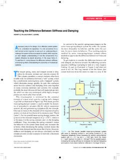
Teaching the Difference Between Stiffness and Damping
hfu.mech.utah.eduFactor”). For the parallel mass-spring-damper system, the Q factor at the resonant frequency is Q m. k c/ , where m is the mass, k is the spring constant, and c is the damping coefficient. Thus, increasing the spring constant k makes the behavior of the system more elastic and increases the Q factor, while decreasing the spring constant makes the

Quality factor, Q
web.ece.ucsb.eduWhen a resonant circuit is connected to the outside world, its total losses (let’s call them RP or GP) are combined with the source and load resistances, RS and RL. For example, Here is a parallel resonant circuit (C,L and RP)connected to the outside. The total Q of this circuit is called the loaded Q or QL and is given by
Chapter 5 Capacitance and Dielectrics
web.mit.eduresistors, filtering out unwanted frequency signals, forming resonant circuits and making frequency-dependent and independent voltage dividers when combined with resistors. Some of these applications will be discussed in latter chapters. Figure …
Alternating Voltage and Current
www.oakton.eduAn important application is a resonant circuit with L and C that is tuned to a particular frequency. 15-2: Alternating-Voltage Generator ... parallel branches is the same as the applied voltage.
Stanley MEYER Resonant Electrolysis Cell System : (page cre
www.rivendellvillage.orgapparently possesses a dielectric constant of about 5--- to produce a parallel resonant circuit. This is excited by a high power pulse generator which, together with the cell capacitance and a rectifier diode, forms a charge pump circuit. High frequency pulses build a rising staircase DC potential across the electrodes of the
An introduction to LLC resonant half-bridge converter
www.st.comparallel to one C, generates the LCC resonant inverter commonly used in electronic lamp ballast for gas-discharge lamps. Its dual configuration, using two inductors and one capacitor, with the load connected in parallel to one L, generates the LLC inverter. As previously stated, for any resonant inverter there is one associated DC-DC resonant