Chapter 9 Asynchronous Sequential Logic
Implementation Procedure Procedure to implement an asynchronous sequential circuits with SR latches: 1. Given a transition table that specifies the excitation function Y = Y 1Y 2…Y k, derive a pair of maps for each S i and R i using the latch excitation table 2. Derive the Boolean functions for each S i and R i
Download Chapter 9 Asynchronous Sequential Logic

Information
Domain:
Source:
Link to this page:
Documents from same domain
Chapter 2 Basic Structure of Computers - NCU
www.ee.ncu.edu.twJin-Fu Li Department of Electrical Engineering National Central University Jungli, Taiwan Chapter 2 Basic Structure of Computers
Chapter 1 Introduction to CMOS Circuit Design
www.ee.ncu.edu.twChapter 1 Introduction to CMOS Circuit Design Jin-Fu Li Advanced Reliable Systems (ARES) Lab. Department of Electrical Engineering National Central University
![Training Course of Design Compiler [相容模式]](/cache/preview/c/f/6/f/4/1/7/2/thumb-cf6f4172c80a30be0667109e5a50ce98.jpg)
Training Course of Design Compiler [相容模式]
www.ee.ncu.edu.twTraining Course of Design Compiler REF: • CIC Training Manual – Logic Synthesis with Design Compiler, July, 2006 • TSMC 0 18um Process 1 8-Volt SAGE-XTM Stand Cell Library Databook September 2003
Chapter 4 Low-Power VLSI DesignPower VLSI Design
www.ee.ncu.edu.twChapter 4 Low-Power VLSI DesignPower VLSI Design Jin-Fu Li Advanced Reliable Syy( )stems (ARES) Lab. Department of Electrical Engineering National Central UniversityNational Central University
![hspice tutorial.ppt [相容模式] - ee.ncu.edu.tw](/cache/preview/0/1/e/d/5/5/6/4/thumb-01ed55640fe3958cfb144af3846e1fcf.jpg)
hspice tutorial.ppt [相容模式] - ee.ncu.edu.tw
www.ee.ncu.edu.twContents Introduction Simulation Input and Controls Waveform Instructions Simulation Output ARES Lab-2010 Hspice Tutorial 2
Chapter 6 VLSI Testing - NCU
www.ee.ncu.edu.twAdvanced Reliable Systems (ARE S) Lab. Jin-Fu Li, EE, NCU 8 Trends of Testing Two key factors are changing the way of VLSI ICs testing The manufacturing test cost has been not scaling
Chapter 4 Electrical Characteristics of CMOS
www.ee.ncu.edu.twFor on-chip metal wires The inductance produces Ldi/dt noise especially for ground bouncing noise. Note that when CMOS circuit are clocked, the current flow changes greatly Inductor) 4 ln(2 d h L ) 4 8 ln(2 h w w h L dt di V L d h h w
Chapter 2 MOS Transistor Theory - NCU
www.ee.ncu.edu.twMOS transistors conduct electrical current by using ... ds than expected at high V ds Mobility degradation At high vertical field strengths (V gs/t ox), ... the electron speed will be high enough to break the electron-hole pair. Moreover, the electrons …

My Hspice 教學 - NCU
www.ee.ncu.edu.twMn1 x in 0 0 nch L=0.18u W=0.22u M=1 Mp2 out ... .ENDSNodes are assigned by using BULK=node in MOSFET or BJT models • Param is used only in sbucircuit and it can be overridden by subckt call or values in .PARAM statement
Related documents
VHDL Syntax Reference - University of Arizona
atlas.physics.arizona.edu1 1. Bits, Vectors, Signals, Operators, Types 1.1 Bits and Vectors in Port Bits and vectors declared in port with direction. Example: port ( a : in std_logic; -- signal comes in to port a from outside b : out std_logic; -- signal is sent out to the port b c : inout std_logic; -- bidirectional port x : in std_logic_vector(7 downto 0); -- 8-bit input vector

DESIGNING SEQUENTIAL LOGIC CIRCUITS
bwrcs.eecs.berkeley.eduDESIGNING SEQUENTIAL LOGIC CIRCUITS Implementation techniques for flip-flops, latches, oscillators, pulse generators, n and Schmitt triggers n Static versus dynamic realization Choosing clocking strategies 7.1 Introduction 7.2 Timing Metrics for Sequential Circuits 7.3 Classification of Memory Elements 7.4 Static Latches and Registers
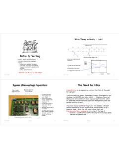
Intro to Verilog - MIT
web.mit.edu-- sequential behavior: always blocks-- pitfalls-- other useful features ... separate behavior from implementation. We need a Hardware Description Language ... known value or when the predicted value is an illegitimate logic value (e.g., due to contention on a tri-state bus). ...

Sequential Logic Implementation
inst.eecs.berkeley.eduSequential Logic Implementation Models for representing sequential circuits Abstraction of sequential elements Finite state machines and their state diagrams Inputs/outputs Mealy, Moore, and synchronous Mealy machines Finite state machine design procedure

Designing Digital Circuits a modern approach
www.arl.wustl.eduthe basic building blocks of a digital circuit using just the rules of logic, and the rules of logic are a whole lot simpler than the laws of physics that ultimately determine how circuits behave. This gives digital circuits a kind of modularity that more general analog circuits lack. It is that modularity

Examples of Solved Problems for Chapter3,5,6,7,and8
www.eecg.utoronto.casequential in this document. Example 3.9 Problem: We introduced standard cell technology in section 3.7. In this technology, circuits are built by interconnecting building-block cells that implement simple functions, like basic logic gates. A commonly used type of standard cell are the and-or-invert (AOI) cells, which can be efficiently

UNIT 4 Memory and Programmable Logic
www.pvpsiddhartha.ac.inUNIT 4 Memory and Programmable Logic Random-Access Memory ... In sequential-access memory, the information stored in some medium is not ... AND array and an OR array to provide an AND-OR sum of product implementation. PROM: fixed AND array constructed as a decoder and programmable OR array.

TLC555 LinCMOS Timer datasheet (Rev. I) - TI.com
www.ti.com• Sequential timing • Time delay generation • Pulse width modulation • Pulse position modulation • Linear ramp generator 3 Description The TLC555 is a monolithic timing circuit fabricated using the TI LinCMOS™ process. The timer is fully compatible with CMOS, TTL, and MOS logic and operates at frequencies up to 2 MHz. Because of its