Graphic Symbols for Electrical and Electronics Diagrams
Symbols for Electrical and Electronics Diagrams of the American National Standards Committee Y32, Graphic Symbols and Designations. There has been close cooperation between the industry and DOD representatives to
Download Graphic Symbols for Electrical and Electronics Diagrams
Information
Domain:
Source:
Link to this page:
Documents from same domain
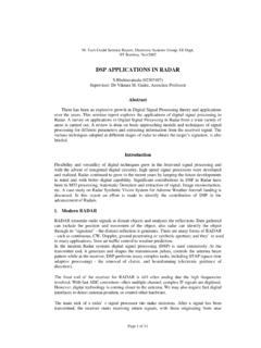
DSP APPLICATIONS IN RADAR
www.ee.iitb.ac.inDSP APPLICATIONS IN RADAR S.Bhaktavatsala (02307407) ... Abstract There has been an explosive growth in Digital Signal Processing theory and applications over the years. This seminar report explores the applications of digital signal processing in ... The main task of a radar's signal processor is to make decisions. After a signal has been
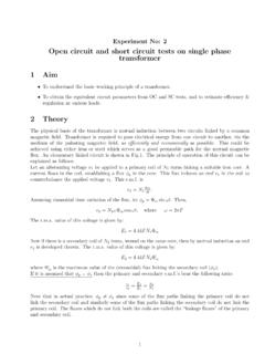
Experiment No: 2 Open circuit and short circuit tests on ...
www.ee.iitb.ac.inOpen circuit and short circuit tests on single phase transformer 1 Aim ... of currents and other performance characteristics of a practical transformer. ... the core loss is very small. Hence, the power input on short circuit is dissipated as heat in the winding.
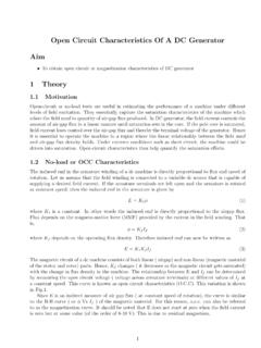
Open Circuit Characteristics Of A DC Generator Aim 1 Theory
www.ee.iitb.ac.inIf the armature terminals are left open and the armature is rotated at constant speed, then the induced emf in the armature is given by E= K 1˚ (1) where K 1 is a constant. In other words the induced emf is directly proportional to the airgap ux. Flux depends on the magneto-motive force (MMF) provided by the current in the eld winding. That is ...

Determination of B-H Curve of Core Material of Transformer ...
www.ee.iitb.ac.inux density in core and A c is the cross-sectional area of the core. So we have E= 4:44B mA cfN (3) The value of induced voltage Eis thus dependent upon B m which can be setup in the core. 2.1 DC Magnetization Curve We know from Biot-Savart’s law that a current carrying conductor produces magnetic eld. \Magnetic
MOSFET Characteristics- Theory and Practice
www.ee.iitb.ac.inOutput DC Characteristics Input Characteristics in Saturation Output Small Signal Characteristics Experiment-Part2 In this part, we investigate the I D −V DS characteristics. The circuit to be used is the same as in Part 1. For a fixed value of V GS, vary V DS to get different values of I D. The expected I D v/s V GS plot is as shown. V DS I D
AN Introduction to VHDL - Overview
www.ee.iitb.ac.inAs a modeling language. For simulation of hardware. For early performance estimation of system architecture. For synthesis of hardware. For fault simulation, test and verification of designs. etc. Dinesh Sharma VHDL

Cyclic Codes - IIT Bombay
www.ee.iitb.ac.inProperties of Cyclic Codes (6) Theorem If g(X) is a polynomial of degree n k and is a factor of Xn +1, then g(X) generates an (n;k) cyclic code. Proof. Multiples of g(X) of degree n 1 or less generate a (n;k) linear block code. We need to show that the generated code is cyclic. For a code polynomial v(X) consider the following equation
Gaussian Random Variables and Processes
www.ee.iitb.ac.inGaussian Random Variables and Processes Saravanan Vijayakumaran [email protected] Department of Electrical Engineering Indian Institute of Technology Bombay August 1, 2012 1/33. Gaussian Random Variables. Gaussian Random Variable Definition A continuous random variable with pdf of the form
EE101: RLC Circuits (with DC sources)
www.ee.iitb.ac.inSeries/Parallel RLC circuits R L C i R L C V iR iL R VC V iC L I 0V * A series RLC circuit driven by a constant current source is trivial to analyze. Since the current through each element is known, the voltage can be found in a straightforward manner. V R = i R; V L = L di dt; V C = 1 C Z i …

No-load And Blocked Rotor Test On An Induction …
www.ee.iitb.ac.inFor wound-rotor construction, one can assume that X s1 ˇX r1 resulting in X s1 = X r1 = 0:5 X br. However, for squirrel cage induction machines, the distribution of X br can be obtained from a look-up table indicating empirical distribution of leakage reactance for the machine type. If X s1 is known, from the no-load test data, we have, X m ...
Related documents
A GRAPHICAL SYMBOLS FOR PIPING SYSTEMS AND PLANT
booksite.elsevier.comAPPENDIX A GRAPHICAL SYMBOLS FOR PIPING SYSTEMS AND PLANT A- 3. Upshot heater Where complex burners are employed the ‘‘burner block’’ may be detailed elsewhere on the drawing, thus ... Fluid contacting vessel (basic symbol) Fluid contacting vessel Support grids and distribution details may be shown Reaction or absorption vessel

NOT MEASUREMENT SENSITIVE MIL-DTL-81310G(AS) 31 March 2008 ...
everyspec.comASME-Y32.2.6 - Graphic Symbols for Heat-Power Apparatus (Copies of the documents listed above are available online www.asme.org or from ASME Information Central Orders/Inquiries, P.O. Box 2300, Fairfield, NJ 07007-2300.)

Practical Hydraulics Course - Fluid Power Education ...
fpti.org2 - Hydraulic Symbols 1) Correctly describe the meanings of: a) a complete graphic symbol b) a simplified graphic symbol c) pictorial symbol. d) cutaway symbol
xxx xxx App 879605 - CAE Users
homepages.cae.wisc.eduAppendix B Table B. Pipe Symbols (continued) Air Conditioning BR B C H C H R C C R D H R D R L R S Heating Air-Relief Line Boiler Blow-Off Compressed Air Condensate or Vacuum Pump Discharge

Hydraulic Symbols
hydraulicsonline.co.uksymbols for hydraulic circuits fluid treatment breather with filter filter (e.g. 2fa...) filter with indicator (e.g. ifrf...+ ifri-d) water / oil cooler air / oil cooler heater ... fluid level check valve shut-off valve single acting telescopic cylinder double acting double rod cylinder closed centre a
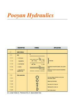
Fluid power graphics - BTP Hydraulics
iranfluidpower.comPooyan Hydraulics 2) L= Length of dash, E = Thickness of line, D = Space between lines DESCRIPTION SYMBOL APPLICATION 1.1 1.1.1 1.1.1.1 1.1.1.2 1.1.1.3

HYDRAULIC CIRCUIT DESIGN AND ANALYSIS
www.arsinmachine.comIt is very important for the fluid power ( Hydraulics and Pneumatics ) designer to have a working knowledge of components and how they operate in a circuit. Hydraulic circuits are developed through the use of graphical symbols for all
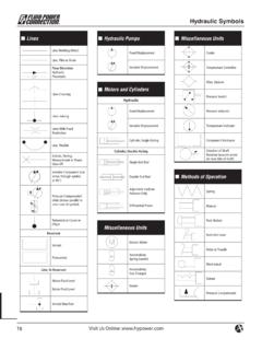
Hydraulic Symbols - HyPOWER
www.hypower.comHydraulic Symbols Lines Line, Working (Main) Line, Pilot or Drain Flow Direction Hydraulic Pneumatic Lines Crossing Lines Joining Lines With Fixed Restriction ... Color Code for Fluid Power Schematic Drawings Black Intensifi ed Pressure Red Supply Intermittent Red Charging Pressure Intermittent Red Reduced Pressure
ENGINEERING YOUR SUCCESS. - parker.com
www.parker.comFluid Power Graphic Symbols Actuator Technical Information Vacuum Technical Information Valve Technival Information H Technical Data Pneumatic Products Fluid Power Graphic Symbols Air Line Pressure Regulator adjustable, relieving Lubricator with automatic filling Lubricator with manual drain Lubricator
Fluid Power Graphic Symbols - parkerhannifin.be
www.parkerhannifin.beFluid Power Graphic Symbols AIR LINE PRESSURE REGULATOR adjustable, relieving LUBRICATOR with automatic filling LUBRICATOR with manual drain LUBRICATOR less drain AUTOMATIC DRAIN OIL REMOVAL FILTER FILTER/SEPARATOR with automatic drain FILTER/SEPARATOR with manual drain AIR LINE PRESSURE REGULATOR pilot controlled,