SiC Power Devices and Modues Application Note
power factor correction (PFC) circuits and secondary side rectifying bridges, and extending to onboard chargers for EV, power conditioners for solar power generation, power supplies for servers, air conditioners, and so on. Currently, SBD with breakdown voltages of 650 V, 1,200 V, and 1,700 V are listed in ROHM’s lineup. Figure 2-1.
Download SiC Power Devices and Modues Application Note

Information
Domain:
Source:
Link to this page:
Documents from same domain
Linear Regulator IC Series Linear Regulator 기초
fscdn.rohm.comLinear Regulator 는 기본적으로 입력, 출력, GND 핀으로 구성되며, 출력이 가변일 경우는 출력전압의 귀환이 필요 하기 때문에 귀환(Feedback)핀이 추가됩니다. (Figure 1) IN OUT FB GND V IN V O Figure 1. Linear Regulator 의 기본구성 Linear Regulator 내부회로의 개요는 Figure 2 …
Op-Amp/Comparator Application Note - Rohm
fscdn.rohm.comop-amp. Generally, an op-amp is composed of three stages: the input stage, the gain stage, and the output stage. The input stage is configured with a differential amplification stage that amplifies the differential voltage between the two terminals. In addition, it does not amplify the common-mode signal component (a condition where no ...
Efficiency of Buck Converter
fscdn.rohm.comEfficiency of Buck Converter Switching regulators are known as being highly efficient power sources. To further improve their efficiency, it is helpful to understand the basic mechanism of power loss. This application note explains power loss factors and methods for calculating them.
Snubber Circuit for Buck Converter IC : Power Management
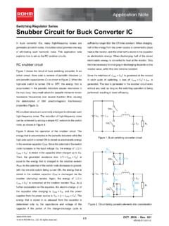
fscdn.rohm.comSnubber Circuit for Buck Converter IC AEK59-D1-0311-0 For example, when the input voltage VIN is 24 V and the switching frequency fSW is 1 MHz, 2 Ë Ì Ç » L680 pF H24 6 H1 MHz L0.39 W the generated consumption power of 0.39 W requires a 6432 size resistor (2512 in inches) with a rated power of 1 W.

ISO 26262: Functional Safety Standard for Modern Road …
fscdn.rohm.comIntrinsic safety is a method for ensuring safety by removing the causes of danger. Functional safety, on the other hand, is a method of reducing risks to an acceptable level to ensure safety ... verification, prototyping, and evaluation are clarified, with reviews performed at each stage. It is also necessary to manage the documents created at
Calculation of Power Loss (Synchronous) : Power Management
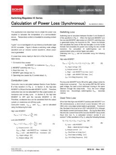
fscdn.rohm.comCalculation of Power Loss (Synchronous) This application note describes how to obtain the power loss required to calculate the temperature of a semiconductor device. Temperature control is important to ensuring product reliability. Figure 1 is a circuit diagram of a synchronous rectification type DC/DC converter. Figure 2 shows a switching node ...
Inductor Calculation for Buck Converter IC
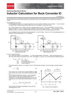
fscdn.rohm.comInductor Calculation of Buck Converter Current-difference between max. and min. (ILP-ILT) is as follows: IN SW D SW IN SW OUT D OUT LP LT V V V L f V V V V V I I (15) Equations (13) and (15) show that large inductance L and high switching frequency will reduce maximum current (ILP)and current difference between max. and min. (ILP-ILT).
Hysteresis Setting for Comparator - Rohm
fscdn.rohm.comprovided only to illustrate the standard usage and operations of the Products. The peripheral conditions must be taken into account when designing circuits for mass production. The technical information specified herein is intended only to show the typical functions of and examples of application circuits for the Products.
Snubber circuit design methods - Rohm
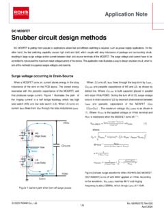
fscdn.rohm.comis bulk capacitor placed in parallel with input HVdc-PGND. During the turn off of LS, surge voltage occurs in drain-source of LS by resonant phenomenon between L MAIN and parasitic capacitance of the MOSFET C OSS ( C DS + DG). The maximum voltage V DS_SURGE is as shown in (1). Where V HVDC is the applied voltage on HVdc terminal and R OFF

ROHM Switching Regulator Solutions Synchronous Buck ...
fscdn.rohm.comROHM Switching Regulator Solutions Synchronous Buck Converter Controller BD9611MUV-EVK-001 Description Using a synchronous rectified step-down DC/DC converter IC BD9611MUV BD 9611MUV-EVK-001 evaluation board 15.0 V ~ output a 24 V input voltage 12.0 V. Provides 10.0A output current. Output current is possible with current settings by selecting
Related documents

Power Factor Correction in Power Conversion Applications ...
ww1.microchip.com© 2007 Microchip Technology Inc. DS01106A-page 3 AN1106 EQUATION 2: POWER FACTOR Harmonic Content Current harmonics are sinusoidal waves that are integral multiples ...
Integrated Power Factor Correction (PFC) and Sensorless ...
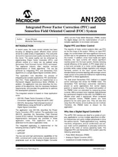
ww1.microchip.com2008 Microchip Technology Inc. DS01208A-page 3 AN1208 A NOVEL APPROACH FOR DIGITAL IMPLEMENTATION OF PFC AND SENSORLESS FOC ALGORITHMS Figure 2 shows a block diagram of the PFC and Sensorless FOC control loops implemented digitally using the dsPIC DSC device.

IEC/EN61000 Standards for Power Supplies
slpower.comSome examples of non-linear loads are switch mode power supplies, without input current waveform or power factor correction (PFC), used in office equipment like computers and printers, lighting ballasts, and battery chargers. The
dsPIC33/PIC24 FRM, High-Speed PWM Module
ww1.microchip.com• Power Factor Correction (PFC) • Interleaved Power Factor Correction (IPFC) • Inverters • DC-to-DC Converters • Battery Chargers • Digital Lighting • Uninterruptable Power Supply (UPS) • AC and DC Motors • Resonant Converters Note: This family reference manual section is meant to serve as a complement to device data sheets.

Power factor correction: A guide for the plant engineer
www.eaton.comWhat can I do to improve power factor? You can improve power factor by adding power factor correction capacitors to your plant distribution system. When apparent power (kVA) is greater than working power (kW), the utility must supply the excess reactive current plus the working current . Power capacitors act as reactive current generators

NCP1632 - Power Factor Controller, Interleaved, 2-Phase
www.onsemi.comPower Factor Controller, Interleaved, 2-Phase NCP1632 The NCP1632 integrates a dual MOSFET driver for interleaved PFC applications. Interleaving consists of paralleling two small stages in lieu of a bigger one, more difficult to design. This approach has several merits like the ease of implementation, the use of smaller

1.5KW to 6KW Any Power Combi Pure Sine Wave …
www.sigineer.comHigh overload ability up to 300% of rated power (20 sec) Low quiescent current, low power “Power Saving Mode” to conserve energy Automatic Generator Start 4-step intelligent battery charger, PFC (Power Factor Correction) for charger 8 pre-set battery type selector switch plus de-sulphation for totally flat batteries

UCC28070 Interleaving Continuous Conduction Mode PFC ...
www.ti.com• External PFC-Disable Interface • Open-Circuit Protection on VSENSE and VINAC pins • Programmable Soft-Start 2 Applications • High-Efficiency Server and Desktop Power Supplies • Telecom Rectifiers • White Goods and Industrial Equipment 3 Description The UCC28070 is an advanced power factor correction (PFC) device that integrates ...