Transcription of 14-Bit, 500 MSPS LVDS, Dual Analog-to-Digital …
1 14 -Bit, 500 MSPS LVDS, dual Analog-to-Digital converter data Sheet AD9684 FEATURES Parallel LVDS (DDR) outputs W total power per channel at 500 MSPS (default settings) SFDR = 85 dBFS at 170 MHz fIN (500 MSPS) SNR = dBFS at 170 MHz fIN (500 MSPS) ENOB = bits at 170 MHz fIN DNL = LSB INL = LSB Noise density = 153 dBFS/Hz at 500 MSPS V, V, and V supply operation No missing codes Internal Analog-to-Digital converter (ADC) voltage reference Flexible input range and t ermination impedance V p-p to V p-p ( V p-p nominal) 400 , 200 , 100 , and 50 differential SYNC input allows multichip synchronization DDR LVDS (ANSI-644 levels) outputs 2 GHz usable analog input full power bandwidth >96 dB channel isolation/crosstalk Amplitude detect bits for efficient AGC implementation Two integrated wideband digital processors per channel 12-bit numerically controlled oscillator (NCO) 3 cascaded half-band filters Differential clock inputs Serial port control Integer clock divide by 2, 4, or 8 Small signal dither APPLICATIONS Communications Diversity multiband, multimode digital receivers 3G/4G, TD-SCDMA, W-CDMA, MC-GSM, LTE General-purpose software radios Ultrawideband satellite receiver Instrumentation (spectrum analyzers, network analyzers, integrated RF test solutions)
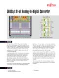
2 Radar digital oscilloscopes High speed data acquisition systems DOCSIS CMTS upstream receiver paths HFC digital reverse path receivers FUNCTIONAL BLOCK DIAGRAM 13015-001 VIN+AVIN AAD9684 CLOCKGENERATIONBUFFERLVDSOUTPUTSLVDS OUTPUTSTAGINGVIN+BVIN BSIGNAL MONITORFASTDETECTBUFFERD0 16D1 D2 D3 D4 D5 D6 D7 D8 D9 D10 D11 D12 D13 DCO STATUS ADCCOREADCCORESIGNALMONITORSPI CONTROLAGNDSDIOSCLKCSBDGNDDRGNDPDWN/STBY SPIVDD( TO )DRVDD( )DVDD( )AVDD3( )AVDD2( )AVDD1( )FD_AFD_BFASTDETECTV_1P0 CLK+CLK 2 4 81414 LVDS/SYNCCONTROLDIGITALDOWN-CONVERTERDIG ITALDOWN-CONVERTERCONTROLREGISTERSSYNC SYNC+Figure 1. GENERAL DESCRIPTION The AD9684 is a dual , 14-bit, 500 MSPS ADC. The device has an on-chip buffer and a sample-and-hold circuit designed for low power, small size, and ease of use. This product is designed for sampling wide bandwidth analog signals. The AD9684 is optimized for wide input bandwidth, a high sampling rate, excellent linearity, and low power in a small package.
3 The dual ADC cores feature a multistage, differential pipelined architecture with integrated output error correction logic. Each ADC features wide bandwidth buffered inputs, supporting a variety of user selectable input ranges. An integrated voltage reference eases design considerations. Each ADC data output is internally connected to an optional decimate by 2 block. The analog input and clock signals are differential inputs. Each ADC data output is internally connected to two digital downconverters (DDCs). Each DDC consists of four cascaded signal processing stages: a 12-bit frequency translator (NCO), and three half-band decimation filters supporting a divide by factor of two, four, and eight. Rev. 0 Document Feedback Information furnished by analog Devices is believed to be accurate and reliable. However, no responsibility is assumed by analog Devices for its use, nor for any infringements of patents or other rights of third parties that may result from its use.
4 Specifications subject to change without notice. No license is granted by implication or otherwise under any patent or patent rights of analog Devices. Trademarks and registered trademarks are the property of their respective owners. One Technology Way, Box 9106, Norwood, MA 02062-9106, Tel: 2015 analog Devices, Inc. All rights reserved. Technical Support AD9684 data Sheet TABLE OF CONTENTS Features .. 1 Applications .. 1 Functional Block Diagram .. 1 General Description .. 1 Revision History .. 2 Product Highlights .. 3 Specifications .. 4 DC Specifications .. 4 AC Specifications .. 5 digital Specifications .. 6 Switching Specifications .. 7 Timing Specifications .. 8 Absolute Maximum Ratings .. 16 Thermal Characteristics .. 16 ESD Caution .. 16 Pin Configuration and Function Descriptions .. 17 Typical Performance Characteristics .. 19 Equivalent Circuits.
5 22 Theory of Operation .. 24 ADC Architecture .. 24 analog Input Considerations .. 24 Voltage Reference .. 26 Clock Input Considerations .. 27 Power-Down/Standby 28 Temperature Diode .. 28 ADC Overrange and Fast Detect .. 29 ADC Overrange .. 29 Fast Threshold Detection (FD_A and FD_B) .. 29 Signal Monitor .. 30 digital Downconverters (DDCs) .. 31 DDC I/Q Input Selection .. 31 DDC I/Q Output Selection .. 31 DDC General Description .. 31 Frequency Translation .. 37 General Description .. 37 DDC NCO Plus Mixer Loss and SFDR .. 38 Numerically Controlled Oscillator .. 38 FIR Filters .. 40 General Description .. 40 Half-Band Filters .. 41 DDC Gain Stage .. 42 DDC Complex to Real Conversion 42 DDC Example Configurations .. 43 digital Outputs .. 47 digital Outputs .. 47 ADC Overrange .. 47 Multichip Synchronization .. 48 SYNC Setup and Hold Window Monitor .. 49 Test Modes .. 51 ADC Test Modes.
6 51 Serial Port Interface (SPI) .. 52 Configuration Using the SPI .. 52 Hardware Interface .. 52 SPI Accessible Features .. 52 Memory Map .. 53 Reading the Memory Map Register Table .. 53 Memory Map Register Table .. 54 Applications Information .. 63 Power Supply Recommendations .. 63 Outline Dimensions .. 64 Ordering Guide .. 64 REVISION HISTORY 5/15 Revision 0: Initial Version Rev. 0 | Page 2 of 64 data Sheet AD9684 The AD9684 has several functions that simplify the automatic gain control (AGC) function in a communications receiver. The programmable threshold detector allows monitoring of the incoming signal power using the fast detect output bits of the ADC. If the input signal level exceeds the programmable threshold, the fast detect indicator goes high. Because this threshold indicator has low latency, the user can quickly reduce the system gain to avoid an overrange condition at the ADC input.
7 In addition to the fast detect outputs, the AD9684 also offers signal monitoring capability. The signal monitoring block provides additional information about the signal that the ADC digitized. The dual ADC output data is routed directly to the one external, 14-bit LVDS output port, supporting double data rate (DDR) formatting. An external data clock and status bit are offered for data capture flexibility. The LVDS outputs have several configurations, depending on the acceptable rate of the receiving logic device and the sampling rate of the ADC. Multiple device synchronization is supported through the SYNC input pins. The AD9684 has flexible power-down options that allow significant power savings when desired. All of these features can be programmed using a V to V capable 3-wire serial port interface ( SPI). The AD9684 is available in a Pb-free, 196-ball ball grid array (BGA) and is specified over the 40 C to +85 C industrial temperature range.
8 This product is protected by a patent. PRODUCT HIGHLIGHTS full power bandwidth supports intermediatefrequency (IF) sampling of signals up to 2 inputs with programmable input termination easefilter design and integrated wideband decimation filters and NCOblocks supporting multiband SPI controls various product features and functions to meet specific system fast overrange detection and input allows synchronization of multiple mm 12 mm, 196-ball 0 | Page 3 of 64 AD9684 data Sheet SPECIFICATIONS DC SPECIFICATIONS AVDD1 = V, AVDD2 = V, AVDD3 = V, DVDD = V, DRVDD = V, SPIVDD = V, specified maximum sampling rate (500 MSPS), V p-p full-scale differential input, V internal reference, AIN = dBFS, default SPI settings, TA = 25 C, unless otherwise noted. Table 1. Parameter Temperature Min Typ Max Unit RESOLUTION Full 14 Bits ACCURACY No Missing Codes Full Guaranteed Offset Error Full 0 + % FSR Offset Matching Full 0 + % FSR Gain Error Full 0 + % FSR Gain Matching Full 0 + % FSR Differential Nonlinearity (DNL) Full + LSB Integral Nonlinearity (INL) Full + LSB TEMPERATURE DRIFT Offset Error 25 C 3 ppm/ C Gain Error 25 C 39 ppm/ C INTERNAL VOLTAGE REFERENCE Full V INPUT-REFERRED NOISE VREF = V 25 C LSB rms analog INPUTS Differential Input Voltage Range (Programmable) Full V p-p Common-Mode Voltage (VCM)
9 25 C V Differential Input Capacitance1 25 C pF analog Input Full Power Bandwidth 25 C 2 GHz POWER SUPPLY AVDD1 Full V AVDD2 Full V AVDD3 Full V DVDD Full V DRVDD Full V SPIVDD Full V IAVDD1 Full 448 503 mA IAVDD2 Full 396 455 mA IAVDD3 Full 103 124 mA IDVDD Full 108 127 mA IDRVDD Full 106 119 mA ISPIVDD Full 2 6 mA POWER CONSUMPTION Total Power Dissipation2 Full W Power-Down Dissipation Full 710 mW Standby Full W 1 Differential capacitance is measured between the VIN+x and VIN x pins (x = A or B). 2 Parallel interleaved LVDS mode. The power dissipation on DRVDD changes with the output data mode used. Rev. 0 | Page 4 of 64 data Sheet AD9684 AC SPECIFICATIONS AVDD1 = V, AVDD2 = V, AVDD3 = V, DVDD = V, DRVDD = V, SPIVDD = V, specified maximum sampling rate (500 MSPS), V p-p full-scale differential input, V internal reference, AIN = dBFS, default SPI settings, TA = 25 C, unless otherwise noted.
10 Table 2. Parameter1 Temperature Min Typ Max Unit analog INPUT FULL SCALE Full V p-p NOISE DENSITY2 Full 153 dBFS/Hz SIGNAL-TO-NOISE RATIO (SNR)3 fIN = 10 MHz 25 C dBFS fIN = 170 MHz Full dBFS fIN = 340 MHz 25 C dBFS fIN = 450 MHz 25 C dBFS fIN = 765 MHz 25 C dBFS fIN = 985 MHz 25 C dBFS fIN = 1950 MHz 25 C dBFS SIGNAL-TO-NOISE RATIO AND DISTORTION RATIO (SINAD)3 fIN = 10 MHz 25 C dBFS fIN = 170 MHz Full 67 dBFS fIN = 340 MHz 25 C dBFS fIN = 450 MHz 25 C dBFS fIN = 765 MHz 25 C dBFS fIN = 985 MHz 25 C dBFS fIN = 1950 MHz 25 C dBFS EFFECTIVE NUMBER OF BITS (ENOB) fIN = 10 MHz 25 C Bits fIN = 170 MHz Full Bits fIN = 340 MHz 25 C Bits fIN = 450 MHz 25 C Bits fIN = 765 MHz 25 C Bits fIN = 985 MHz 25 C Bits fIN = 1950 MHz 25 C Bits SPURIOUS-FREE DYNAMIC RANGE (SFDR)3 fIN = 10 MHz 25 C 83 dBFS fIN = 170 MHz Full 76 85 dBFS fIN = 340 MHz 25 C 82 dBFS fIN = 450 MHz 25 C 86 dBFS fIN = 765 MHz 25 C 81 dBFS fIN = 985 MHz 25 C 76 dBFS fIN = 1950 MHz 25 C 69 dBFS WORST HARMONIC, SECOND OR THIRD3 fIN = 10 MHz 25 C 83 dBFS fIN = 170 MHz Full 85 76 dBFS fIN = 340 MHz 25 C 82 dBFS fIN = 450 MHz 25 C 86 dBFS fIN = 765 MHz 25 C 81 dBFS fIN = 985 MHz 25 C 76 dBFS fIN = 1950 MHz 25 C 69 dBFS Rev.